Closing element assembly for compound needles used in knitting machines

US6925841B2Inactive Publication Date: 2005-08-09CHIMA

Image

  • Closing element assembly for compound needles used in knitting machines
  • Closing element assembly for compound needles used in knitting machines
  • Closing element assembly for compound needles used in knitting machines

Examples


Embodiment Construction

[0030]Reference will now be made in detail to the presently preferred embodiments of the invention, one or more examples of which are shown in the Figures. Each example is provided to explain the invention, and not as a limitation of the invention. In fact, features illustrated or described as part of one embodiment can be used with another embodiment to yield still a further embodiment. It is intended that the present invention cover such modifications and variations.

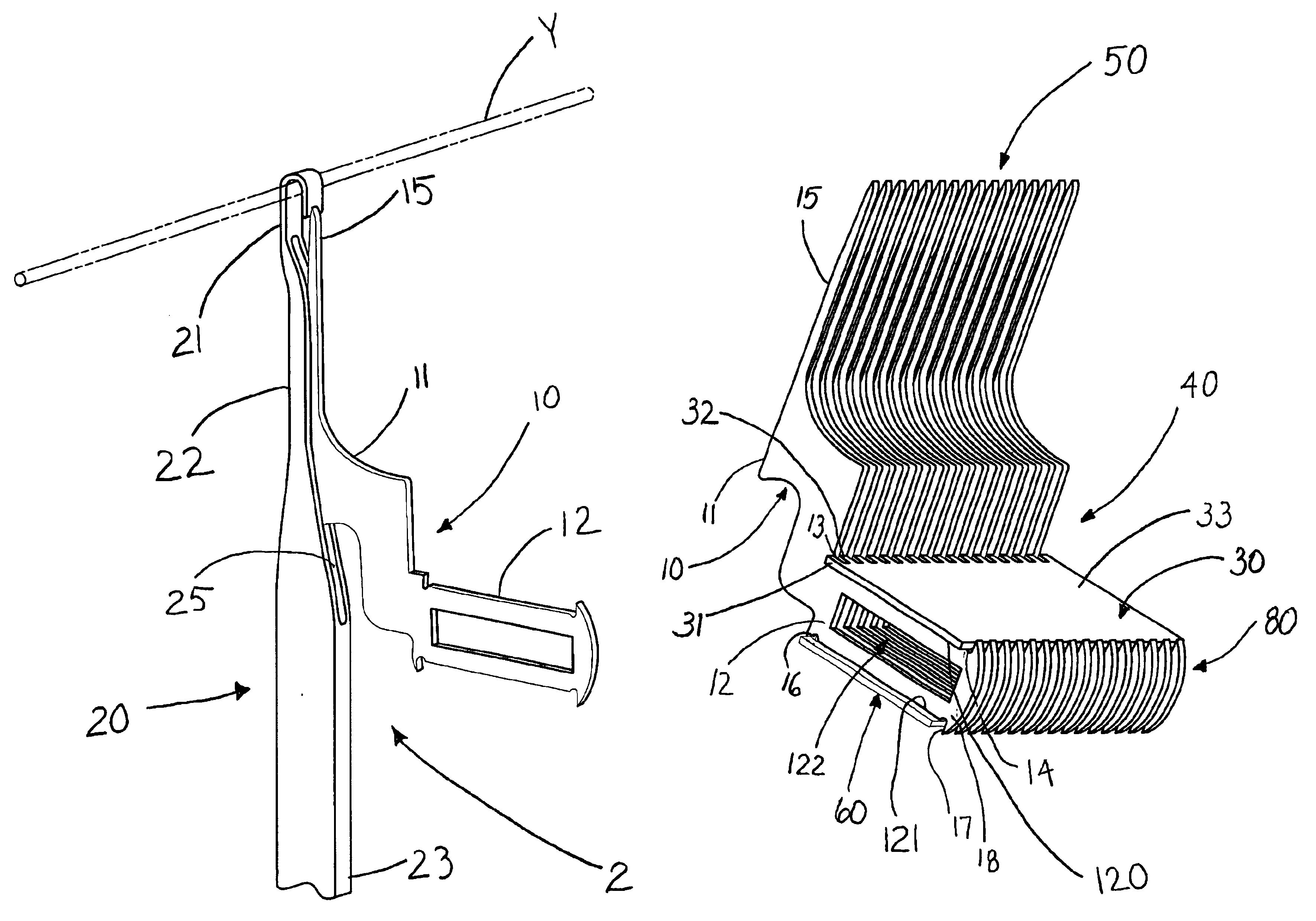
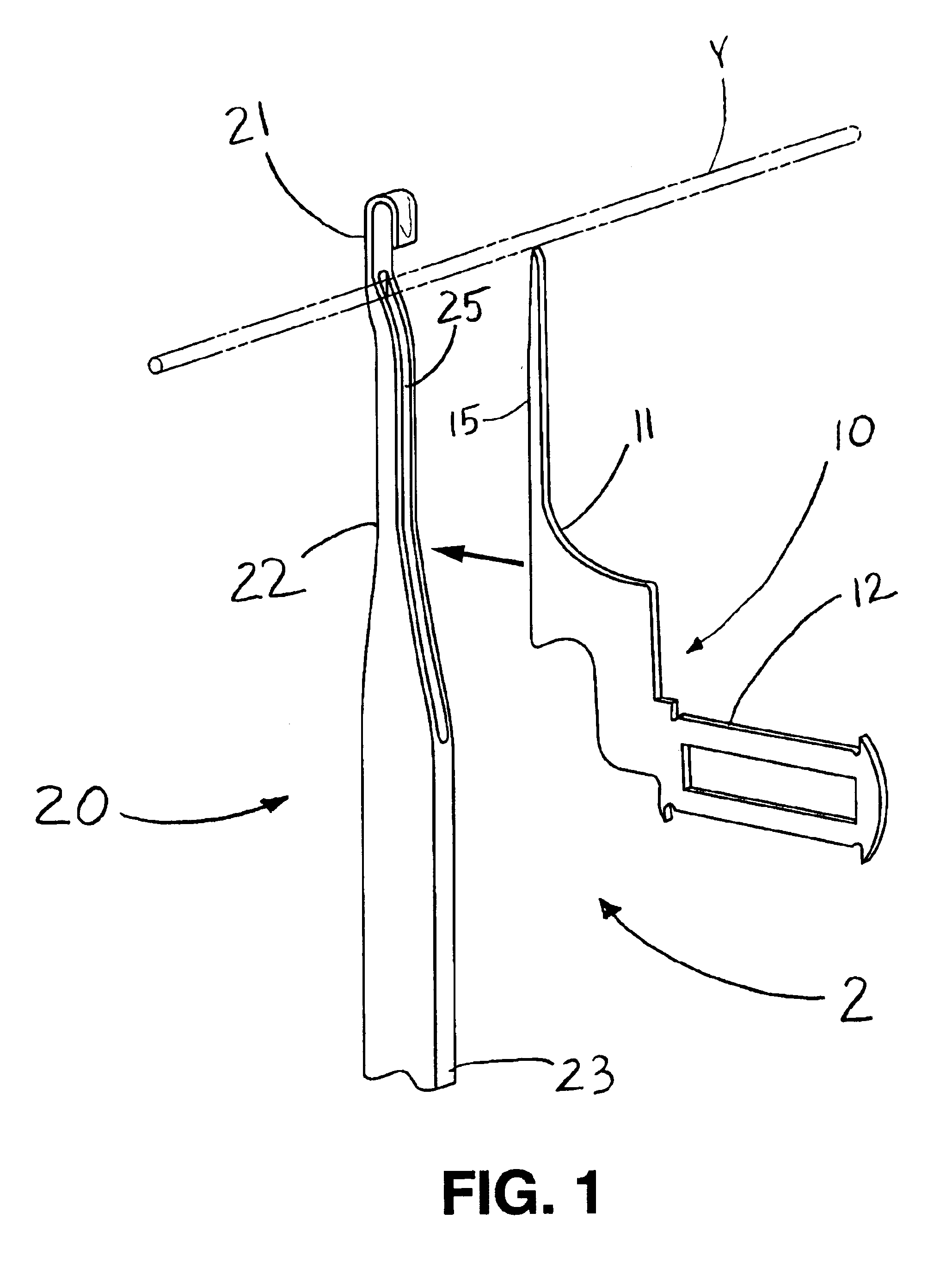
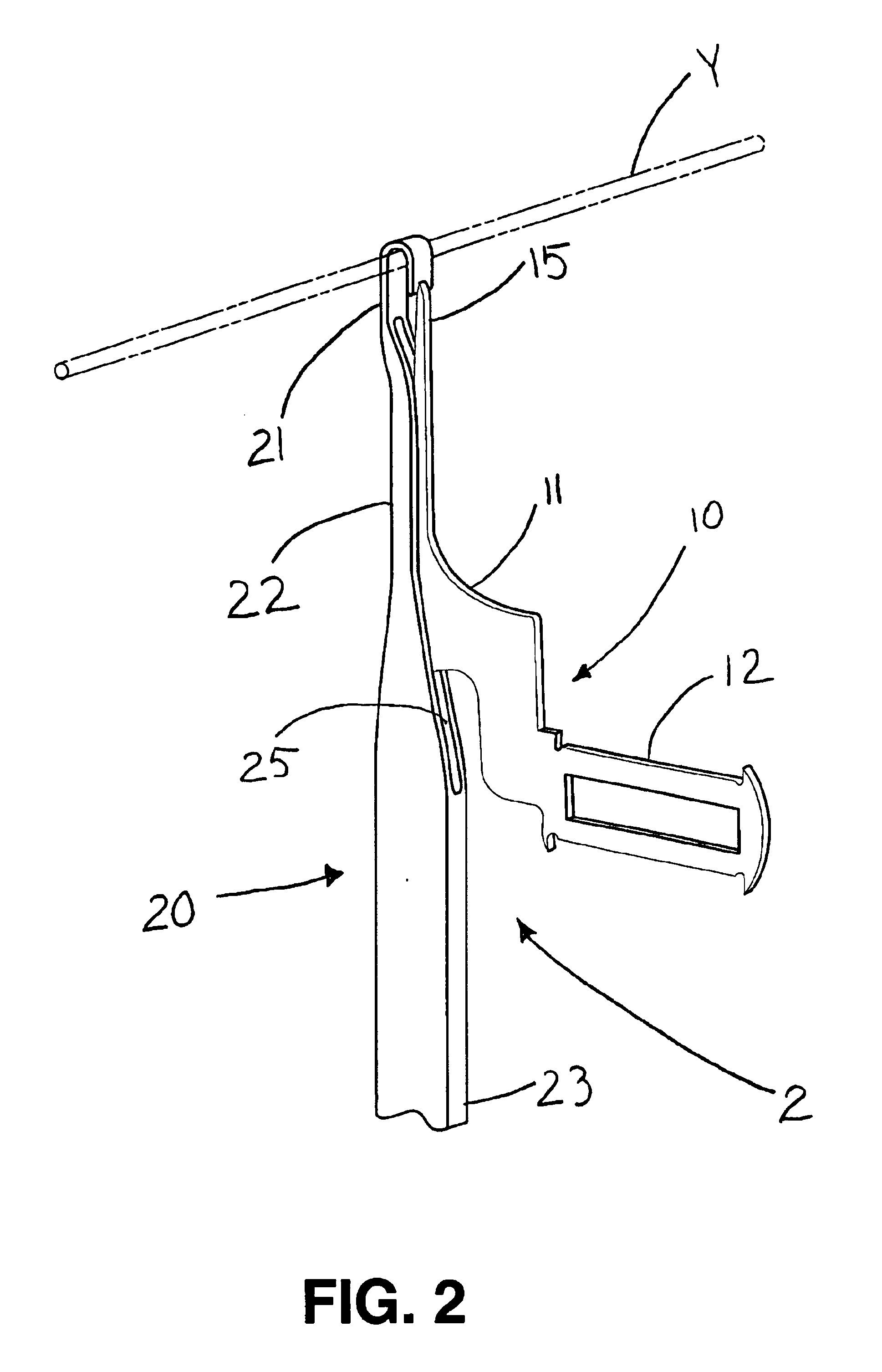
[0031]FIGS. 1 and 2 show a compound needle that operates within a warp-knitting machine. FIG. 1 shows, in an exploded view, a compound needle generally 2, which is used in warp knitting machines and has two discrete parts. Compound needle 2 possesses a hooking element generally 20 and a closing element, or closure blade, generally 10. The hooking element 20 has a hook 21 at its one end for catching and maneuvering a yarn Y during the warp knitting process. A stem 22 extends from the hook 21 down to a butt 23. As illust...


PUM


Abstract

A closing element assembly is provided for closing hooking elements within a knitting machine. The assembly has a plurality of closing elements with each closing element having a butt end and a working end. The butt end defines at least one indention along the length of the butt end. At least one plate is provided for receipt in the indention. The plate defines closing element channels therein for receipt of a portion of the butt ends of the plurality of closing elements. The plate secures the plurality of closing elements in proper position for cooperating with a plurality of hooking elements of compound needles within a knitting process.

Description

BACKGROUND OF THE INVENTION[0001]Needles have always been an integral part of the warp knitting process. In the past different types of needles have been used in different machines. Two predominate types of warp knitting machines in use today are the Tricot machine and the Raschel machine. Historically, the Tricot machines used bearded needles in forming a warp knit, while Raschel machines only used latch needles. With the production of modern warp knitting machines, however, compound needles replaced bearded needles in Tricot machines and also penetrated into the Raschel machine market.[0002]Compound needles allowed for faster production on a warp-knitting machine due to their unique construction making them more desirable to warp knit manufacturers using Tricot machines. A compound needle possesses two distinct parts which form the needle: the hooking element and the closing element, or closure blade. The hooking element and closing element of a compound needle work in concert to ...

Claims


Application Information

Patent Timeline
09 Aug 2005
Publication
US6925841B2
IPC
D04B35/00; D04B35/06
CPC
D04B35/06; D04B37/06
Inventors
HEYDT, JR., DOUGLAS L.