
Barbed tape

a barbed wire and tape technology, applied in barbed wire, building types, constructions, etc., can solve the problems of less material, less visual intimidation, and short barbs, and achieve the effect of reducing manufacturing costs and less material

Inactive Publication Date: 2005-08-09
ALLIED TUBE CONDUIT
View PDF41 Cites 5 Cited by
  • Summary
  • Abstract
  • Description
  • Claims
  • Application Information

AI Technical Summary

Benefits of technology

The design provides a stronger, more resistant barrier that is cost-effective to produce and deters intrusions with its intimidating appearance and increased rigidity, while the cutouts create a secondary penetration point for intruders.

Problems solved by technology

In addition to lacking the visual intimidation common to more modern barbed tape barriers, barbed wire lacks the strength to resist crushing.
It is more visually intimidating than barbed wire, which features short, unimposing barbs.
Barbed tape barriers also are typically stronger and harder to crush than barbed wire.
Disadvantages of this barrier include the relatively unimposing appearance of the smaller barbs, and the narrow center strip.
Also, the coils are relatively weak in vertical compression.
One deficiency of this barrier is its loss of strength caused by the reduced flange width.
Weaker barriers are easier to breach and barriers that collapse easily are less fit for the purpose of preventing the crossing of the barrier.

Method used


Image

  • Barbed tape
  • Barbed tape
  • Barbed tape

Examples


Embodiment Construction

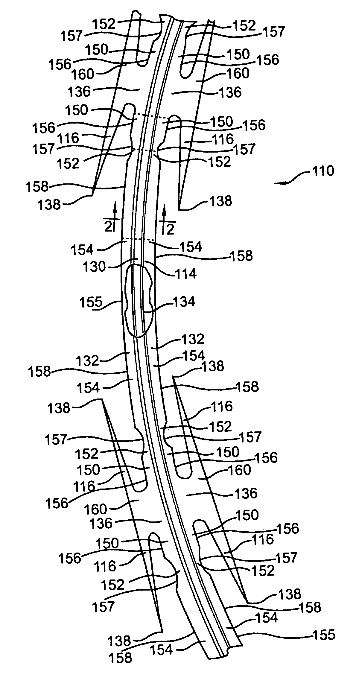
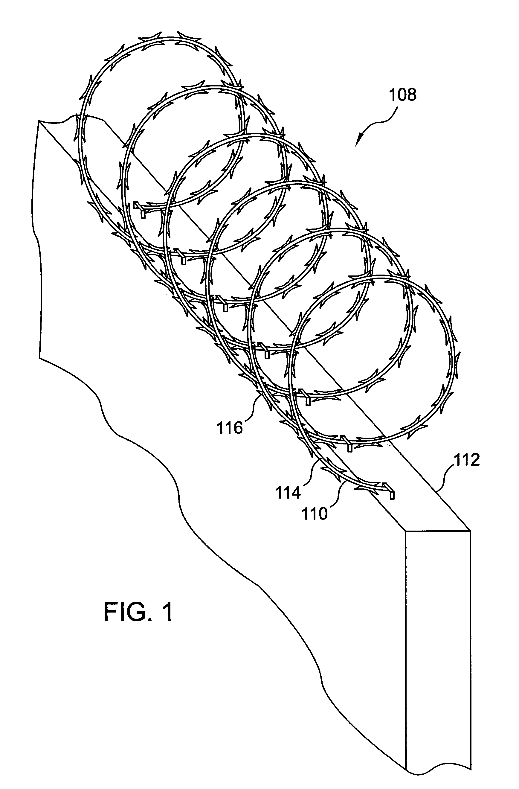
[0018]Referring to FIG. 1, a barrier 108 includes barbed tape 110 mounted on a wall 112. Barbed tape 110 preferably includes an elongated strip of metal or metal body 114, which has been bent slightly along its longitudinal axis in such a way that the strip substantially forms a helix. Barbs 116 extend from opposing sides of body 114. Preferably the barbs are in clusters of four barbs, with a pair of barbs extending from each side of body 114. Each pair of barbs includes two barbs 116 extending in each opposing longitudinal direction. The helical structure is optimal for preventing intrusions across the barrier because barbs 116 at the top of barrier 108 extend directly toward a would-be intruder. Structural patterns other than helical are also possible. For example, the structure could be a concertina pattern where adjacent loops of helical coils are attached to one another at specified points on the circumference.

[0019]The helical structure is also used to facilitate storage and s...


PUM


Abstract

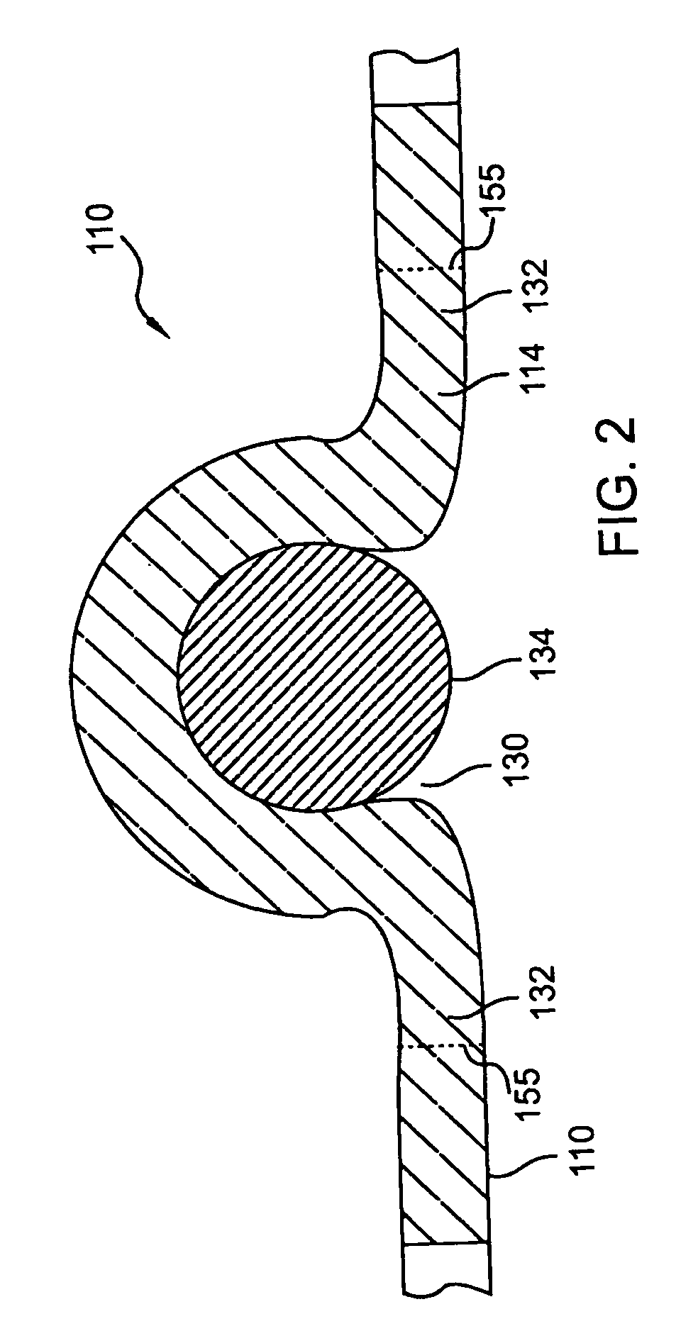
A barrier structure includes a continuous piece of elongated metal tape. The metal tape includes barbs spaced along an elongate body. Each of the barbs is connected securely to a barb root, and each barb root is connected securely to the elongate body. A first region of the elongate body is adjacent to each barb root, and a second region of the elongate body is adjacent to each first region distal from the barb root. A third region of the elongate body adjacent to each second region distal from the first region extends lengthwise from each second region and meets a corresponding third region that is extending lengthwise away from another second region. Each second region extends transversely and inwardly from the adjacent first region and the adjacent third region.

Description

CROSS REFERENCE TO RELATED APPLICATION[0001]This application is a continuation of a patent application by Pavlov, entitled “BARBED TAPE”, Ser. No. 09 / 642,162, filed Aug. 18, 2000, now U.S. Pat. No. 6,601,830, which is hereby incorporated herein by reference.BACKGROUND OF THE INVENTION[0002]1. Technical Field[0003]This invention generally relates to barriers and security fences, and more specifically relates to barbed tape.[0004]2. Background Art[0005]An early form of metal barrier fence was made of barbed wire. This type of barrier has been in use for more than a century, and is typically rather easy to breach. In addition to lacking the visual intimidation common to more modern barbed tape barriers, barbed wire lacks the strength to resist crushing. To defeat its intended purpose, one need only lay some heavy object over the wire strands, thereby providing a walkway over the barrier.[0006]Barbed tape is designed to overcome these deficiencies. It is more visually intimidating than ...

Claims


Application Information

Patent Timeline
Patent Type & Authority Patents(United States)
IPC IPC(8): B21F25/00F41H11/08F41H11/00
CPCB21F25/00F41H11/08
Inventor PAVLOV, MICHAEL V.
Owner ALLIED TUBE CONDUIT
Learn More