Hydroformed space frame and rearward ring assembly therefor

Inactive Publication Date: 2005-08-09
MAGNA INTERNATIONAL INC
View PDF12 Cites 50 Cited by
  • Summary
  • Abstract
  • Description
  • Claims
  • Application Information

AI Technical Summary

Benefits of technology

[0011]To meet the needs identified above, the invention provides a space frame for a motor vehicle comprising a pair of laterally spaced, longitudinally extending side rail structures, a pair of forward-most upright structures and a pair of roof rail structures. Each forward-most upright structure is connected to a respective side rail structure, thereby forming a pair of A pillars and a forward end of each roof rail structure is connected to an upper end of an associated A pillar. A rearward ring assembly is connected at upper portions thereof with the roof rail structures and at bottom portions thereof with the side rail structures. The rearward ring assembly includes a tubular hydroformed inverted U-shaped upper member, a pair of tubular hydroformed side members and a cross structure. The tubular hydroformed upper member has a cross portio

Problems solved by technology

Although tubular blanks can be hydroformed so that the transverse cross-sectional geometry and the longitudinal shape (for example, the longitudinal curvature) of the finally-formed hydroformed member varies greatly, some space frame components must have a very complex geometry which cannot easily be achieved by using a component comprised of a hydroformed member formed from a single tubular blank.
The more complex the geometry of the blank due to pre-bending and the longer the length of the tu

Method used


Image

  • Hydroformed space frame and rearward ring assembly therefor
  • Hydroformed space frame and rearward ring assembly therefor
  • Hydroformed space frame and rearward ring assembly therefor

Examples


Embodiment Construction

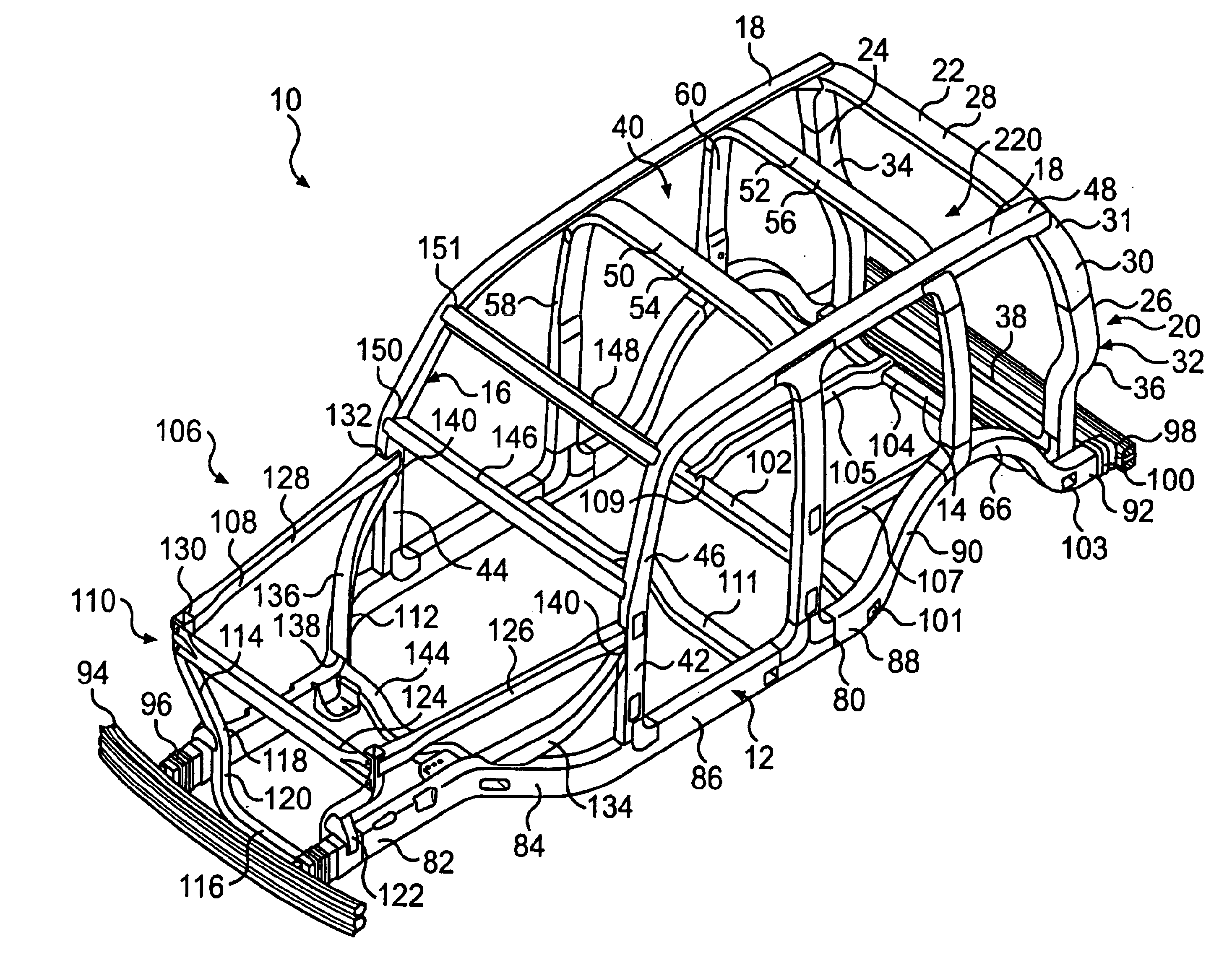
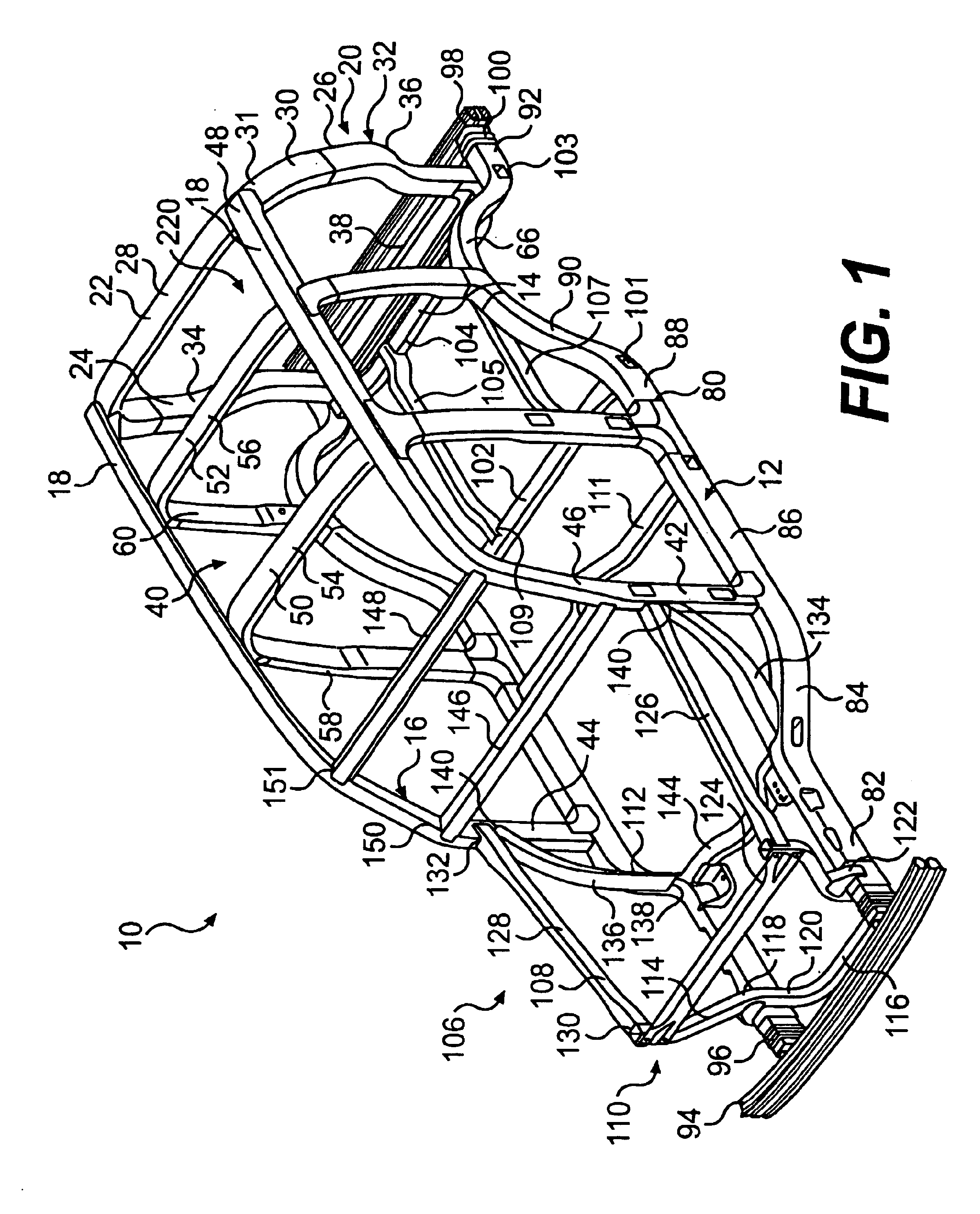
[0024]FIG. 1 shows a space frame, generally designated 10, constructed according to the principles of the present invention. The space frame 10 generally includes a pair of laterally spaced, longitudinally extending side rail structures 12, a laterally extending rearward connecting structure 14 connected between rearward portions of the side rail structures 12 and a pair of forward-most upright structures 16. Each forward-most upright structure 16 is connected to a respective side rail structure 12 and extends generally upwardly therefrom to form a pair of A pillars. A pair of roof rail structures 18 are disposed on each side of the space frame 10 in generally vertically spaced relation above the side rail structures 12 and are connected to the space frame 10 in a manner described below.

[0025]The space frame 10 includes a rearward ring assembly 20. The rearward ring assembly 20 is shown in isolation in FIGS. 5-9 and is described in detail below. It can be appreciated from FIG. 1 tha...


PUM


Abstract

A space frame for a motor vehicle having a pair of laterally spaced, longitudinally extending side rail structures, a pair of forward-most upright structures each being connected to a respective side rail structure, thereby forming a pair of A pillars, a pair of roof rail structures, a forward end of each roof rail structure being connected to an upper end of an associated A pillar, and a rearward ring assembly connected at upper portions thereof with the roof rail structures and at bottom portions thereof with the side rail structures. The rearward ring assembly having (a) a tubular hydroformed inverted U-shaped upper member having a cross portion and a pair of leg portions extending downwardly from opposite ends of the cross portion, (b) a pair of tubular hydroformed side members, and (c) a cross structure rigidly connected in ring-forming relation between the second ends of the side members.

Description

[0001]This application is the National Phase of International Application PCT / US01 / 43043 filed 9 Nov. 2001 which designated the U.S. and that International Application was published under PCT Article 21(2) in English on May 16, 2002 as International Publication Number WO 02 / 38434 A2. This application also claims priority to U.S. Provisional Application No. 60 / 247,045, filed 13 Nov. 2000, which document is herein incorporated by reference.FIELD OF THE INVENTION[0002]The present invention is generally related to motor vehicle frames and more particularly to space frames that utilize tubular hydroformed members.BACKGROUND OF THE INVENTION[0003]Space frame architecture is increasingly being used in vehicle manufacturing and represents a relatively new approach to vehicle construction. A space frame is an assembly of individual frame components that are connected at joints to form a cage-like structure on which the other vehicle components, such as the engine, the drive train, the suspen...

Claims


Application Information

Patent Timeline
IPC IPC(8): B62D21/11B62D23/00B62D31/00
CPCB62D21/11B62D23/005
Inventor GABBIANELLI, GIANFRANCOASHLEY, RICHARD D.
Owner MAGNA INTERNATIONAL INC
Why Eureka
Try Eureka