Liquid ejection head

a technology of liquid ejection and nozzle, which is applied in the direction of inhalator, spray nozzle, printing, etc., to achieve the effect of increasing speed

Inactive Publication Date: 2005-08-09
CANON KK
View PDF13 Cites 28 Cited by
  • Summary
  • Abstract
  • Description
  • Claims
  • Application Information

AI Technical Summary

Benefits of technology

[0006]The primary object of the present invention is to provide a liquid ejection head which ejects extremely small liquid droplets, more specifically, liquid droplets, the sizes of which are on the order of no more than a pico-liter. Once a liquid ejection head capable of ejecting liquid droplets, the sizes of which are on the order of no more than a pico-liter, is realized, not only will the application or such a liquid ejection head quickly spread in the field of ink jet recording, but also it will spread into fields other than the field of ink jet recording.

Problems solved by technology

Therefore, the problem that the small hole of the restrictor portion becomes plugged as the liquid therein dries up, docs not occur.

Method used


Image

  • Liquid ejection head
  • Liquid ejection head
  • Liquid ejection head

Examples


Embodiment Construction

[0020]Hereinafter, the embodiments of the present invention will be described with reference to the appended drawings.

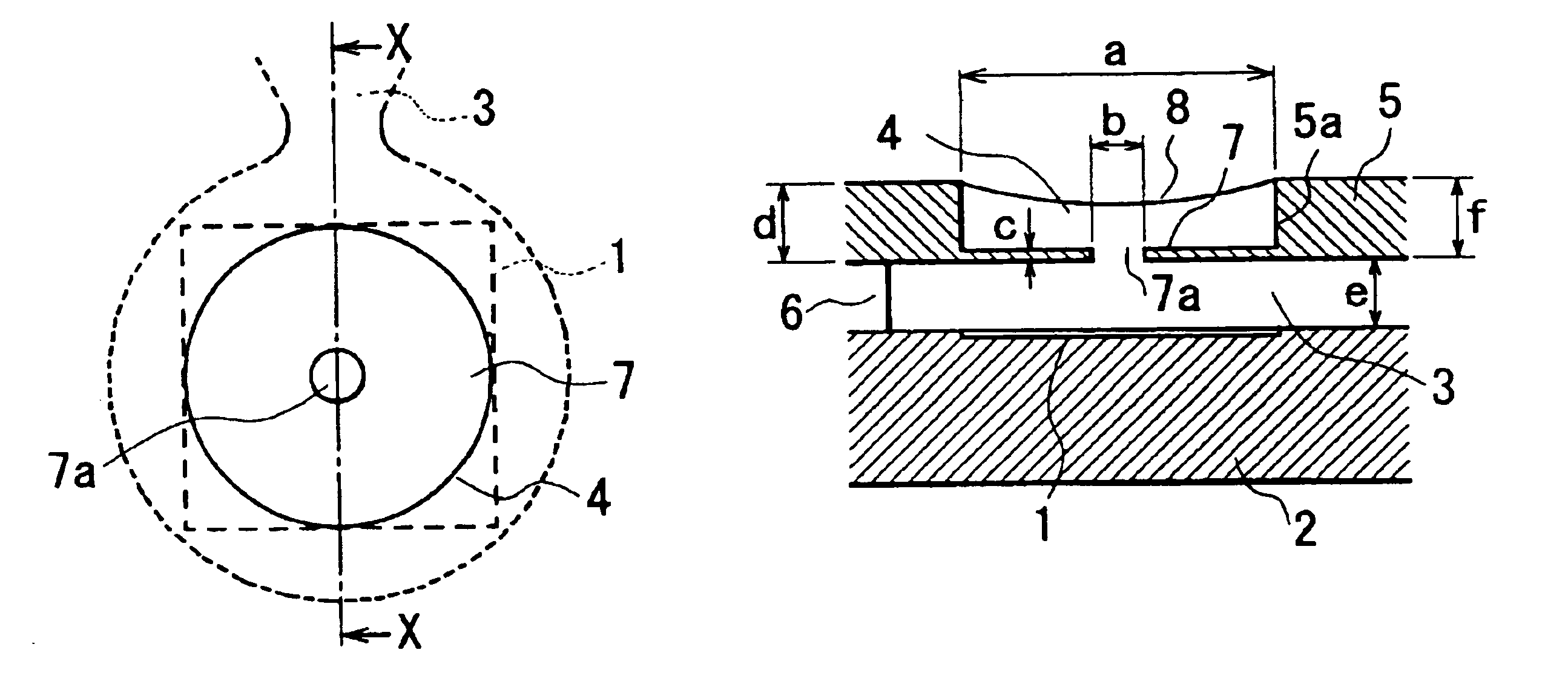
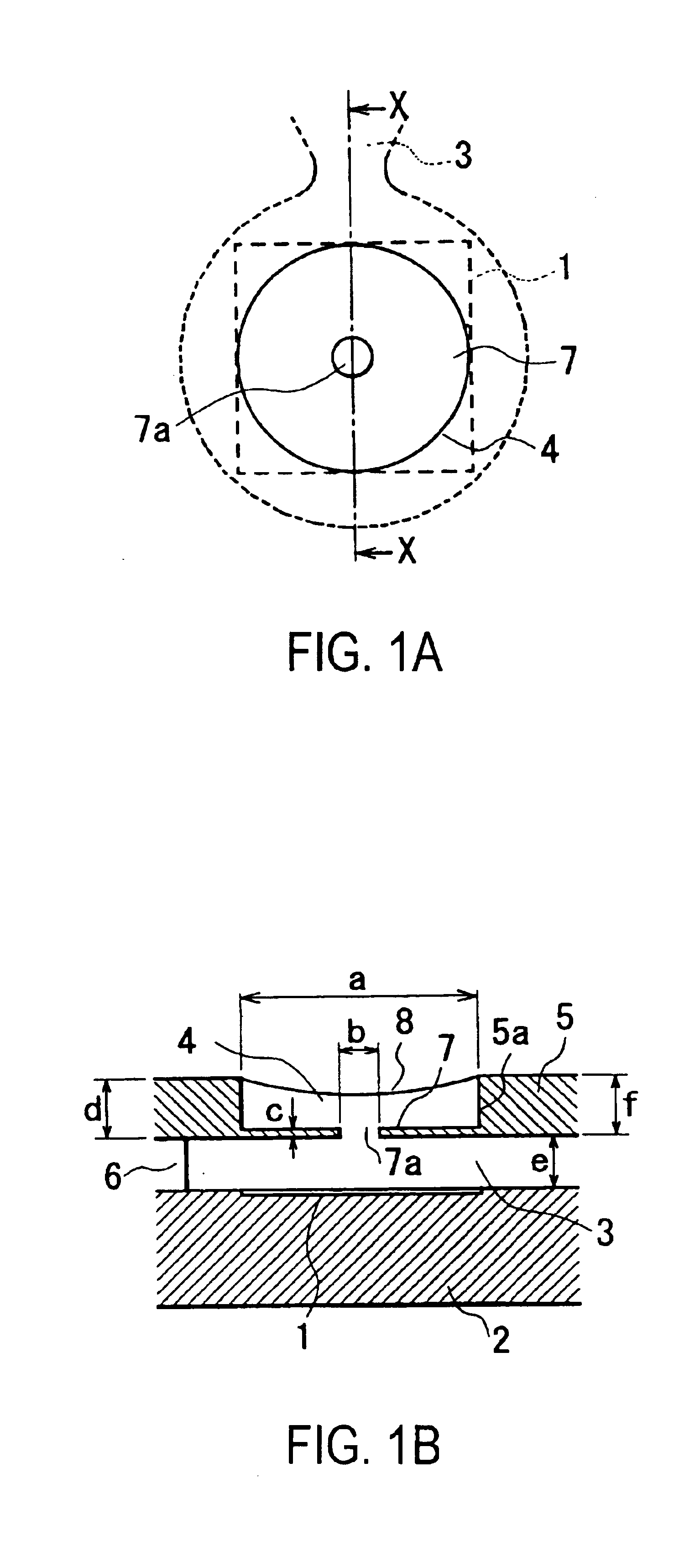
[0021]FIG. 1 shows the liquid ejection head in an embodiment or the present invention, FIG. 1(a) being a plan view thereof, and FIG. 1(b) being a sectional view thereof, at the plane X—X in FIG. 1(a).

[0022]The liquid ejection head shown in FIG. 1 comprises a substrate 2, and a heater 1, as an element for generating the energy for liquid ejection. The heater 1 is disposed in the liquid path. Although FIG. 1 shows the combination of one heater 1 and one liquid path 3, there are disposed a plurality of the heaters 1, one for each liquid path 3, on a single piece of substrate 2. The choice of the energy generating element does not need to be limited to an electrothermal transducing element. For example, it may be a vibratory energy generating element such as a piezoelectric element.

[0023]Each liquid path 3 in surrounded by an ejection outlet plate 5 having the ejection o...


PUM


Abstract

A liquid ejection head includes a liquid path; an ejection outlet forming member which constitutes a part of a wall of the liquid and which forms an ejection outlet for ejecting a droplet of liquid; a heat generating element, provided at a position opposing to the ejection outlet of the wall of the liquid flow path, for generating a bubble in the liquid by application of heat to the liquid; a restrictor portion, provided at a recessed portion of the ejection outlet, wherein the recessed portion is recessed from a plane in which the ejection outlet is formed, wherein the liquid forms a meniscus and is retained in the ejection outlet such that the restrictor portion is within the liquid, wherein an area So of an opening of the restrictor portion and a surface Sh of the heat generating element satisfy So≦Sh. According to this invention, a central portion of the meniscus opposed to the fine opening at the ejection outlet bulges, and the liquid is ejected in this state. Namely, very small amount of the liquid can be ejected, since not all of the liquid in the recess portion in the ejection outlet is ejected.

Description

[0001]This application is a continuation application of pending International Application No. PCT / JP02 / 12235, filed on Nov. 22, 2002.TECHNICAL FIELD[0002]The present invention relates to a liquid ejection head for ejecting liquid, in the form of a minute liquid droplet. A liquid ejection head is preferably employed as an ink jet head in the field of ink jet recording for ejecting recording ink. It is also preferably employed, in the field of medicine, as the liquid ejection head of an inhaling apparatus, or the like, used for atomizing liquid medicine so that the medicine can be inhaled into lungs.BACKGROUND ART[0003]A liquid ejection head for ejecting liquid, in the form of a minute liquid droplet, has been widely employed as an ink jet head in the field of ink jet recording. Not only is an ink jet head required to simply eject liquid droplets, but also it is required to be stable in the direction in which liquid droplets are ejected. Thus, various proposals have been made to meet ...

Claims


Application Information

Patent Timeline
Patent Type & Authority Patents(United States)
IPC IPC(8): A61M15/02A61M15/00B41J2/14B05B1/00B05B1/24
CPCA61M15/0065A61M15/02B41J2/14016B41J2/1404B41J2/1412B41J2/1433B41J2002/14387A61M15/025B41J2002/14475B41J2/05
Inventor SASAKI, TOSHIAKIMURAI, KEIICHITAMURA, YASUYUKISUGAMA, SADAYUKIASAI, AKIRAKAWAI, TSUTOMUTACHIHARA, MASAYOSHI
Owner CANON KK
Why Eureka
Try Eureka