
Fuse applications of reactive composite structures

Inactive Publication Date: 2006-03-30
REACTIVE NANOTECH
View PDF25 Cites 25 Cited by
  • Summary
  • Abstract
  • Description
  • Claims
  • Application Information

AI Technical Summary

Benefits of technology

[0014] In accordance with the invention, a fuse comprises a reactive composite structure to interrupt the flow of current in a circuit. The term fuse, as used herein, is intended to cover current interrupters generically and thus encompasses fuses, circuit breakers and other devices for interrupting the flow of current through a conductor. Reactive composite structures comprise two or more phases of materials spaced in a controlled fashion throughout a composite in uniform layers, local layers, islands, or particles. Upon appropriate excitation, the materials undergo an exothermic chemical reaction that spreads rapidly through the composite structure generating heat and light. Moreover a reactive composite structure can break apart upon reaction. This breakage can rapidly interrupt the flow of current through the reactive composite structure. Such structures can provide high-speed current interruption.
[0015] In addition, reactive composite structures can have abrupt reaction initiation thresholds such that a pulse of energy of a certain magnitude may initiate a clearing reaction but a slightly smaller pulse of energy may not. Such a reactive composite structure can thus provide a high speed, highly sensitive current interrupter.

Problems solved by technology

This breakage can rapidly interrupt the flow of current through the reactive composite structure.
Such structures can provide high-speed current interruption.

Method used


Image

  • Fuse applications of reactive composite structures
  • Fuse applications of reactive composite structures
  • Fuse applications of reactive composite structures

Examples


Embodiment Construction

[0029] This description is divided into three parts. Part I describes the nature of reactive composite structures and ways of making them. Part II provides a variety of illustrative fuse applications, and Part III describes beneficial features of reactive composite structures and methods for tailoring those features for particular applications.

I. The Nature of Reactive Composite Structures and Ways of Making Them

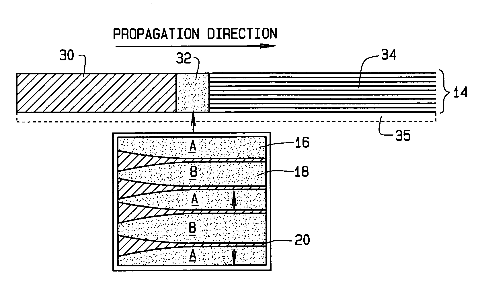
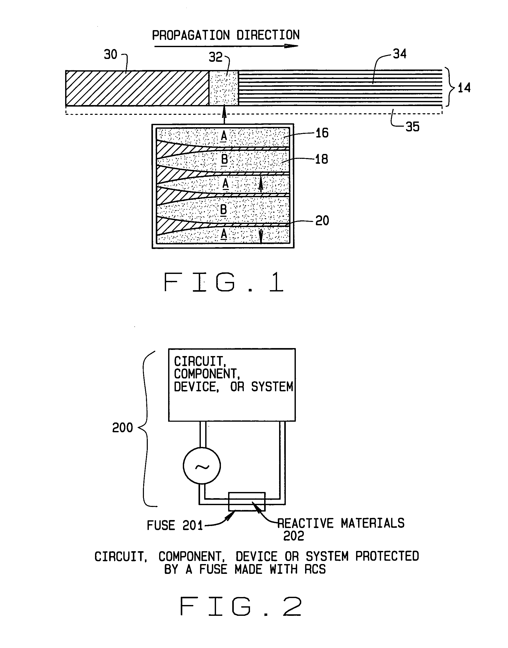
[0030] The external geometries of reactive composite structures can be in any one of a variety of forms including composite foils, composite wires, composite rods and composite bulk form bodies. Referring to the drawings, FIG. 1 illustrates a reactive composite foil 14 composed of alternating phases or layers 16 and 18 of materials A and B, respectively, that can exothermically react. These alternating layers 16 and 18 can be any materials amenable to mixing of neighboring atoms (or having changes in chemical bonding) in response to a stimulus. The materials A / B can, for ...


PUM

PropertyMeasurementUnit
Electrical conductivityaaaaaaaaaa
Flow rateaaaaaaaaaa
Coloraaaaaaaaaa

Abstract

In accordance with the invention, a fuse comprises a reactive composite structure to interrupt the flow of current in a circuit. The term fuse, as used herein, is intended to cover current interrupters generically and thus encompasses fuses, circuit breakers and other devices for interrupting the flow of current through a conductor. Reactive composite structures comprise two or more phases of materials spaced in a controlled fashion throughout a composite in uniform layers, local layers, islands, or particles. Upon appropriate excitation, the materials undergo an exothermic chemical reaction that spreads rapidly through the composite structure generating heat and light. Moreover a reactive composite structure can break apart upon reaction. This breakage can rapidly interrupt the flow of current through the reactive composite structure. Such structures can provide high-speed current interruption. In addition, reactive composite structures can have abrupt reaction initiation thresholds such that a pulse of energy of a certain magnitude may initiate a clearing reaction but a slightly smaller pulse of energy may not. Such a reactive composite structure can thus provide a high speed, highly sensitive current interrupter.

Description

CROSS-REFERENCE TO RELATED APPLICATIONS [0001] This application claims the benefit of U.S. provisional Patent Application Ser. No. 60 / 692,857 filed by T. Weihs et al. on Jun. 22, 2005 (“Applications of Reactive Composite Structures”) which is incorporated herein by reference. [0002] This application is a continuation-in-part of U.S. patent application Ser. No. 10 / 247,998 filed by T. Weihs et al. on Sep. 4, 2003, (“Methods of Making and Using Freestanding Reactive Multilayer Foils”). The '998 application, in turn, is a continuation-in-part of three U.S. patent applications: 1) U.S. application Ser. No. 09 / 846,486 filed by T. Weihs et al. on May 1, 2001 (“Freestanding Reactive Multilayer Foils”); 2) U.S. application Ser. No. 09 / 846,422 filed by T. Weihs et al. on May 1, 2001 (“Reactive Multilayer Structures for Ease of Processing and Enhanced Ductility”) and 3) U.S. application Ser. No. 09 / 846,447 filed by T. Weihs et al. on May 1, 2001 (“Method of Making Reactive Multilayer Foil and ...

Claims


Application Information

Patent Timeline
IPC IPC(8): B32B3/00
CPCY10T428/24917H01H85/06
Inventor WEIHS, TIMOTHY P.HEIAN, ELLEN M.VINCENT, RAMZIVALLIAPPAN, SOMASUNDARAMBESNOIN, ETIENNE
Owner REACTIVE NANOTECH
Learn More