Liquid-feeding device and liquid ejection apparatus

a technology of liquid feeding device and liquid ejection device, which is applied in the direction of packaging, coating, printing, etc., can solve the problems of complex manufacturing process, small ink capacity within the device, and complicated mechanism

Inactive Publication Date: 2005-08-09
SONY CORP
View PDF3 Cites 5 Cited by
  • Summary
  • Abstract
  • Description
  • Claims
  • Application Information

AI Technical Summary

Benefits of technology

[0015]Accordingly, it is an object of the present invention to provide an ink-feeding device with large liquid-capacity and a simplified structure and capable of stably holding liquid without leakage.
[0016]In addition, in order to solve the problems described above, Japanese Patent Application No. 2001-322361, to the same assignee as in the present invention, has been already disclosed. The present invention has been made to further improve this application so that even if a valve does not normally function, the gas-liquid interchange can be performed by preventing liquid leakage.
[0023]Therefore, even when the closing member holds the open region open, since the liquid meniscus is held at the lower end of the air inlet tube, air cannot enter the liquid reservoir from the lower end of the air inlet tube. The pressure in the liquid-feeding device is thereby maintained appropriately, preventing liquid from leaking out.

Problems solved by technology

However, the conventional technique described above has the following problems.
Therefore, there has been a problem that the ink capacity within the device is small relative to the entire size of the ink-feeding device.
Also, since the second example is a system using the spring 207, there are problems in manufacturing that if the ink reservoir 205 is reduced in thickness, for example, the spring 207 cannot be accommodated within the bag 206, and the manufacturing process is complicated.
Furthermore, this is a structure in that the spring 207 is accommodated inside the bag 206, so that there have been problems that the mechanism is complicated and the cost is also increased.

Method used


Image

  • Liquid-feeding device and liquid ejection apparatus
  • Liquid-feeding device and liquid ejection apparatus
  • Liquid-feeding device and liquid ejection apparatus

Examples


first embodiment

(First Embodiment)

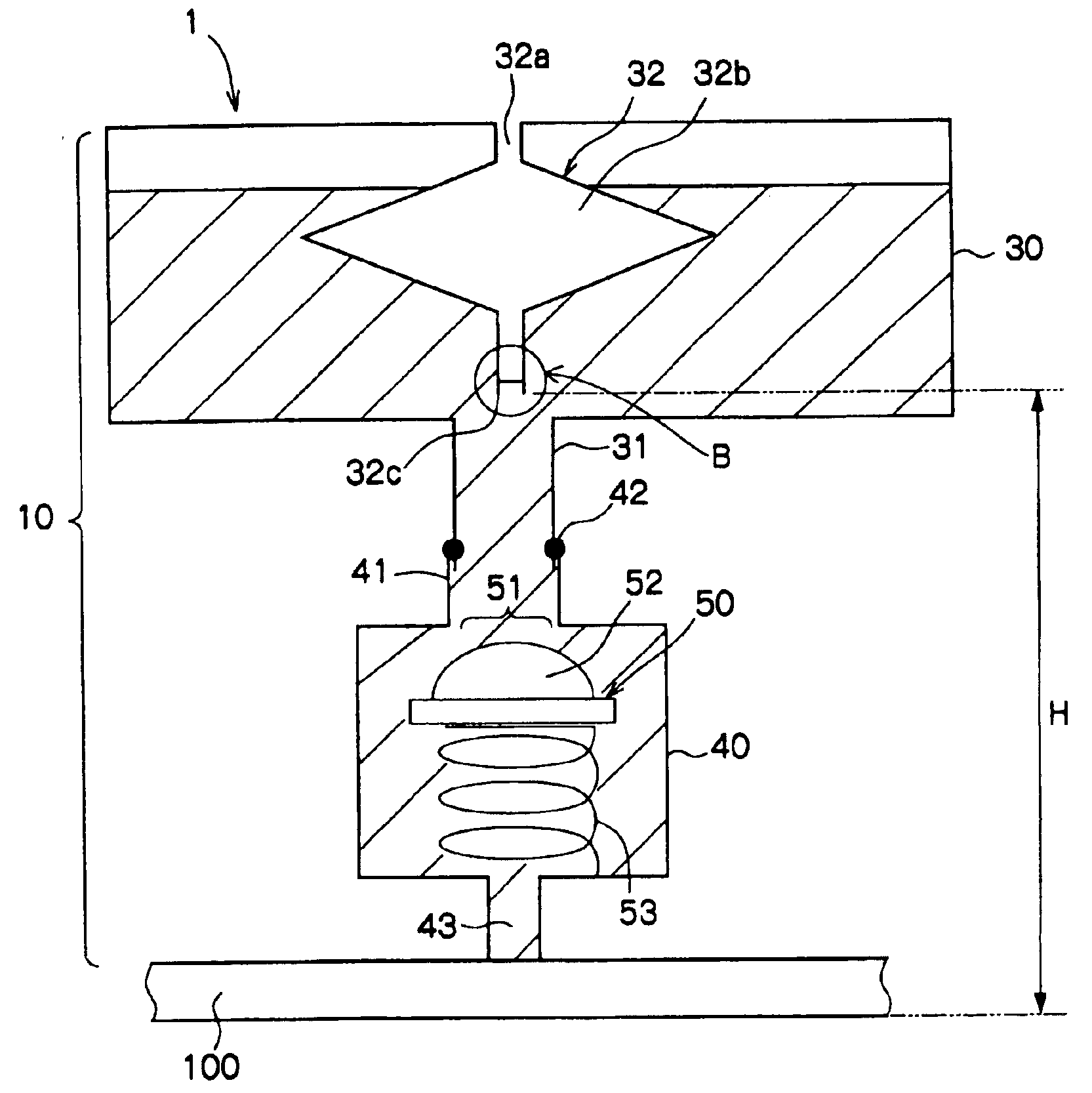
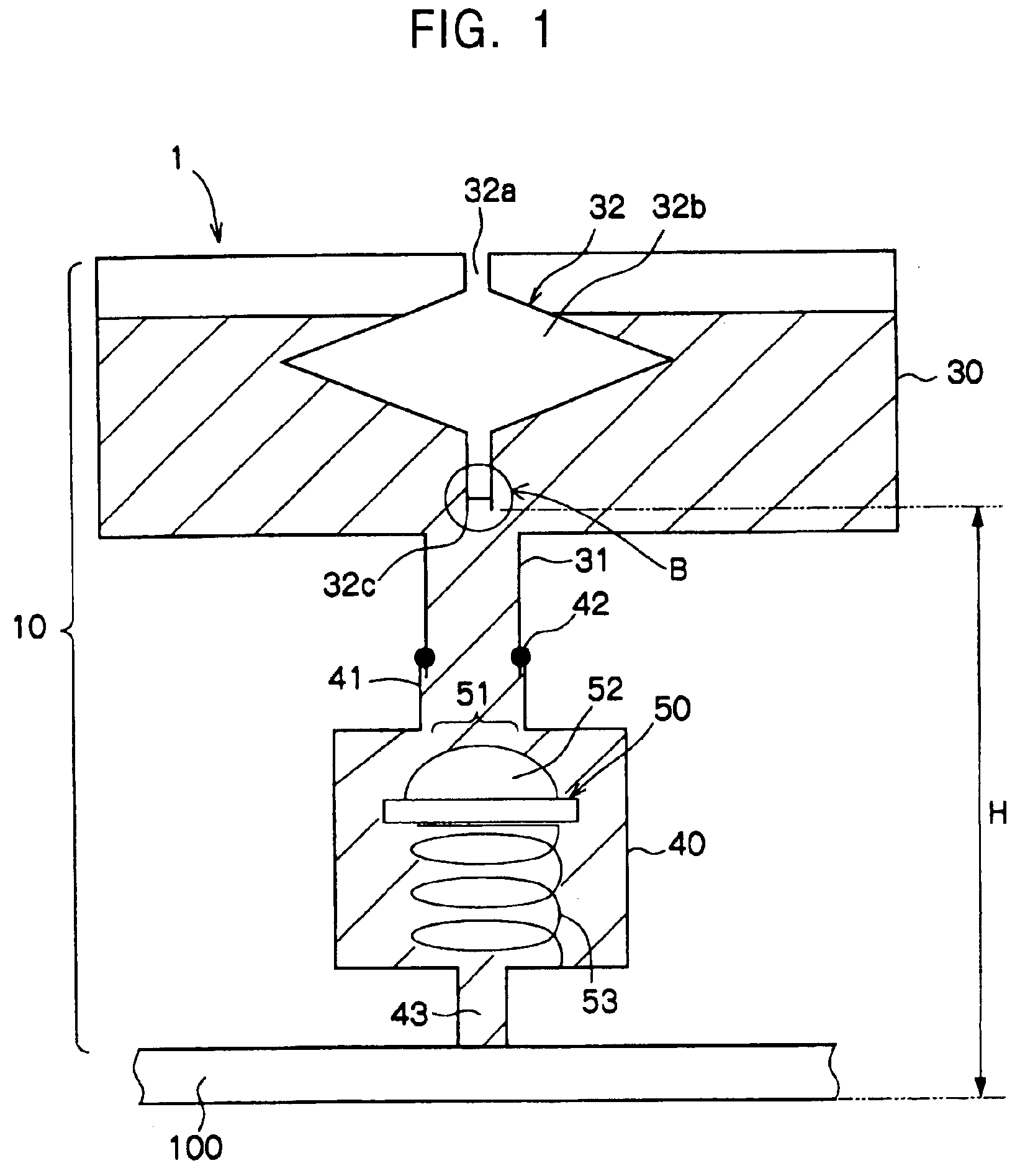
[0039]FIG. 1 is a front sectional view of an inkjet printer head (simply referred to below as a printer head) 1 according to a first embodiment of the present invention. The printer head 1 comprises an ink-feeding device 10 and an ink ejection unit 100. The ink ejection unit 100 corresponds to a liquid ejection unit according to the present invention and only a contour thereof is shown in FIG. 1.

[0040]The ink-feeding device 10 comprises an ink reservoir (ink tank) 30, an ink chamber 40, and a valve 50. Wherein the ink reservoir and the ink chamber correspond to a liquid reservoir and a liquid chamber according to the present invention, respectively.

[0041]In the ink reservoir 30 constructed to be container shaped, ink is charged. Referring to FIG. 1 and so forth, the ink within the ink reservoir 30 is indicated by oblique lines.

[0042]On the bottom surface of the ink reservoir 30, a cylindrical nozzle 31 is provided, which is connected to a connection part 41 integra...

second embodiment

(Second Embodiment)

[0102]FIG. 12 is a front sectional view of a printer head 1A according to a second embodiment of the present invention. According to the second embodiment, an ink-feeding device 10A different from that of the first embodiment is provided.

[0103]The ink-feeding device 10A has an air inlet tube 32A different from that of the first embodiment, and other elements are the same as those of the first embodiment.

[0104]The air inlet tube 32A has not a buffer section differently from the air inlet tube 32 according to the first embodiment. The air inlet tube 32A is structured to be cylindrical and has a constant cross-section along the longitudinal direction except for the vicinity of the lower end 32c. The space of the cross-section of the air inlet tube 32A is larger than that of the air inlet tube 32 according to the first embodiment except for the buffer section 32b.

[0105]In such a manner, the air inlet tube 32A has not the buffer section 32b according to the second emb...


PUM


Abstract

There is provided a liquid-feeding device with large liquid-capacity and a simplified structure and capable of stably holding liquid without leakage. An ink-feeding device includes an ink reservoir; an ink chamber; a valve displaced so that a closing member opens an open region by reduction in pressure due to reduction in the ink amount in the ink chamber; a fresh-air communicating hole for communicating with fresh air; and an air inlet tube capable of bringing air, when an amount of ink in the ink chamber is reduced, from the fresh-air communicating hole by the amount of air corresponding to the amount of the reduced ink, wherein a bore diameter of the lower end of the air inlet tube and a water head are determined so that the ink meniscus holding power P at the lower end of the air inlet tube and the water head pressure H corresponding to the height from the bottom surface of an ink ejection unit (nozzle surface) to the lower end of the air inlet tube satisfy the relationship P>H.

Description

[0001]This application claims priority to Japanese Patent Application Number JP2002-136489 filed May 13, 2002 which is incorporated herein by reference.BACKGROUND OF THE INVENTION[0002]1. Field of the Invention[0003]The present invention relates to a liquid-feeding device for feeding liquid to an external device such as a liquid ejection unit and a liquid ejection apparatus incorporating the liquid feeding device, such as an inkjet printer head, and more specifically it relates to a technique for stably holding a large amount of liquid without liquid leakage and with a simplified low-cost structure.[0004]2.Description of the Related Art[0005]As an ink-feeding device for use in a conventional printer head, the following device has been known, for example.[0006]FIG. 13 is a sectional view of an internal structure of a first example of a conventional ink-feeding device of the type. Referring to FIG. 13, an ink reservoir 201 partitioned into an ink tank 201a and an ink container 201b. T...

Claims


Application Information

Patent Timeline
Patent Type & Authority Patents(United States)
IPC IPC(8): B41J2/175B05C5/00B05C11/10
CPCB41J2/17596
Inventor ANDO, MAKOTONAMEKAWA, TAKUMI
Owner SONY CORP
Why Eureka
Try Eureka