Disk plate concrete dowel system

a technology of concrete dowels and discs, which is applied in the direction of paving details, constructions, roads, etc., can solve the problems of horizontal movement relative to pour joints, and achieve the effect of convenient positioning of pocket formers

Inactive Publication Date: 2005-08-09
SHAW & SONS
View PDF26 Cites 83 Cited by
  • Summary
  • Abstract
  • Description
  • Claims
  • Application Information

AI Technical Summary

Benefits of technology

[0018]The dowel plate has a generally rounded shape that is divided into an embedded portion and a slidable portion. The slidable portion is configured to be laterally slidable within the pocket former while the embedded portion is configured to be substantially encapsulated or embedded within the second pour such that it is rigidly affixed therewithin after the concrete cures or hardens. Advantageously, the dowel plate is provided in a generally rounded shape in order to minimize safety hazards to construction site equipment and personnel who may be injured by contact with an otherwise rough, exposed edge of a dowel plate having sharp corners or a dowel rod having exposed ends. Furthermore, the dowel plate may preferably be shaped such that a width thereof is at a maximum adjacent the pour joint where the bearing, shear and flexural stresses are greatest.
[0019]The pocket former has a horizontally-extending interior compartment bounded by a pair of spaced apart, upper and lower former plates defining generally planar, upper and lower inner surfaces. The interior compartment has an open, generally straight side defining a compartment opening. The interior compartment may have an arch-shaped compartment perimeter extending from opposing ends of the straight side such that the interior compartment is generally crescent-shaped. The interior compartment is configured with the spacing between the upper and lower former plates being complementary to a thickness of the dowel plate such that a relatively snug, sliding fit is provided therebetween. In this manner, the pocket former creates a void in the first pour such that the dowel plate may be simply slid into the form until a perimeter of the dowel plate is generally in abutment with the compartment perimeter.
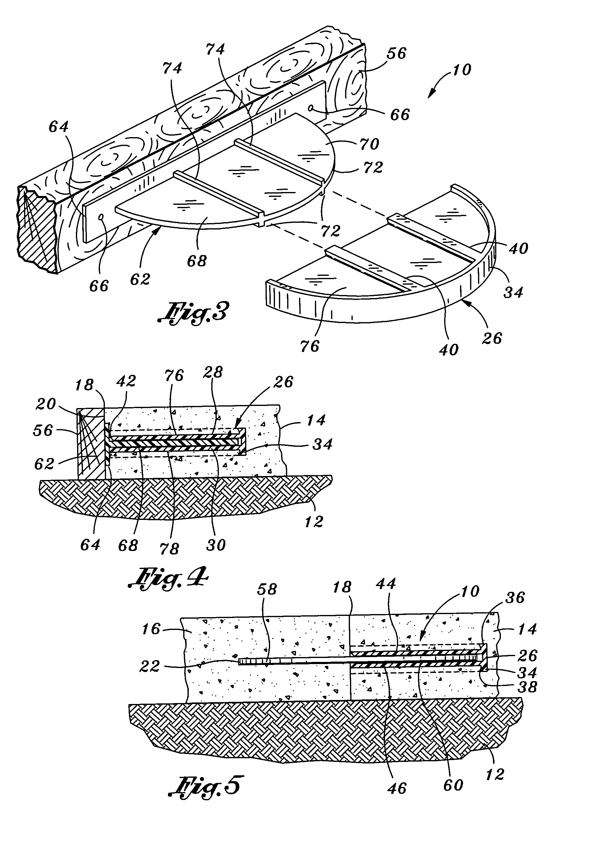
[0021]The disc dowel system may include a positioner bracket that is mounted to a removable concrete form. The positioner bracket facilitates positioning the pocket former during pouring of the first pour. In certain methods of concrete pavement construction, pour joints are typically formed by using a wooden stud or a sheet metal form as the removable concrete form. Such concrete form is typically staked to the substrate along a desired location of the pour joint. The pocket former is positioned adjacent the concrete form such that the interior compartment is substantially horizontally outwardly extending away from the concrete form. Wet concrete is then poured on a side of the concrete form to create the first pour which encapsulates the pocket former. The concrete form is then removed, exposing a pour face of the pour joint along the first pour with the dowel plate opening formed in the pour face. After the slidable portion of the dowel plate is inserted through the dowel plate opening and into the pocket former, the embedded portion remains exposed on an opposite side of the pour joint. Wet concrete is then poured on the opposite side of the pour joint to create the second pour which rigidly encapsulates the embedded portion of the dowel plate therewithin.

Problems solved by technology

Horizontal movement relative to the pour joint may occur due to uncontrolled shrinkage or contraction of the concrete mixture as water is lost during curing.

Method used


Image

  • Disk plate concrete dowel system
  • Disk plate concrete dowel system
  • Disk plate concrete dowel system

Examples


Embodiment Construction

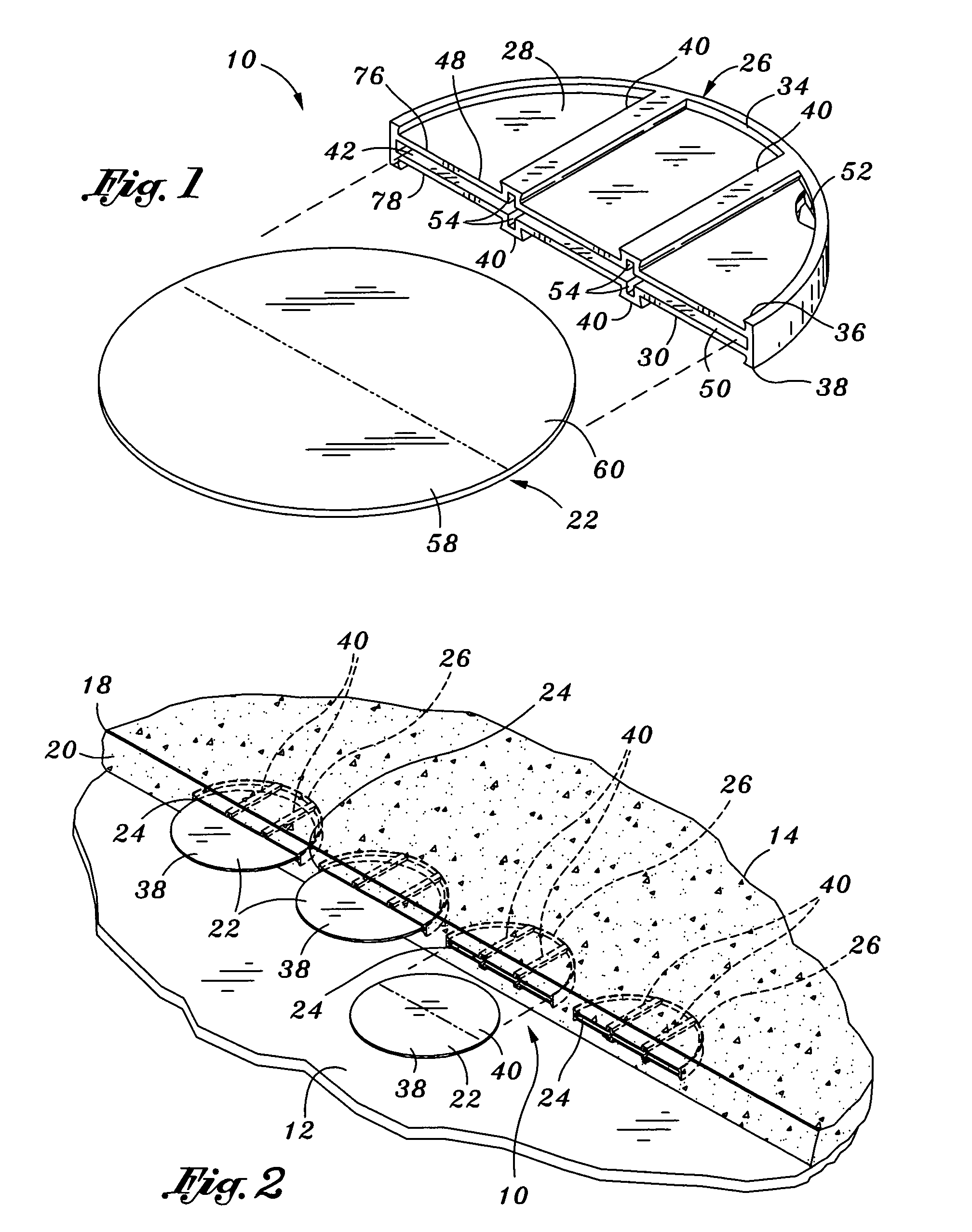
[0029]Referring now to the drawings wherein the showings are for purposes of illustrating the present invention and not for purposes of limiting the same, FIG. 1 illustrates a dowel plate 22 and corresponding pocket former 26 of the disc dowel system 10 of the present invention. The disc dowel system 10 is installed at a pour joint 18 between a first concrete pour 14 and a second concrete pour 16 disposed above a subgrade or a substrate 12, as can be seen in FIG. 5. The substrate 12 may be soil underlying the first and second pours 14, 16. Alternatively, the substrate 12 may be a metal decking or other surface that is adapted to support concrete.

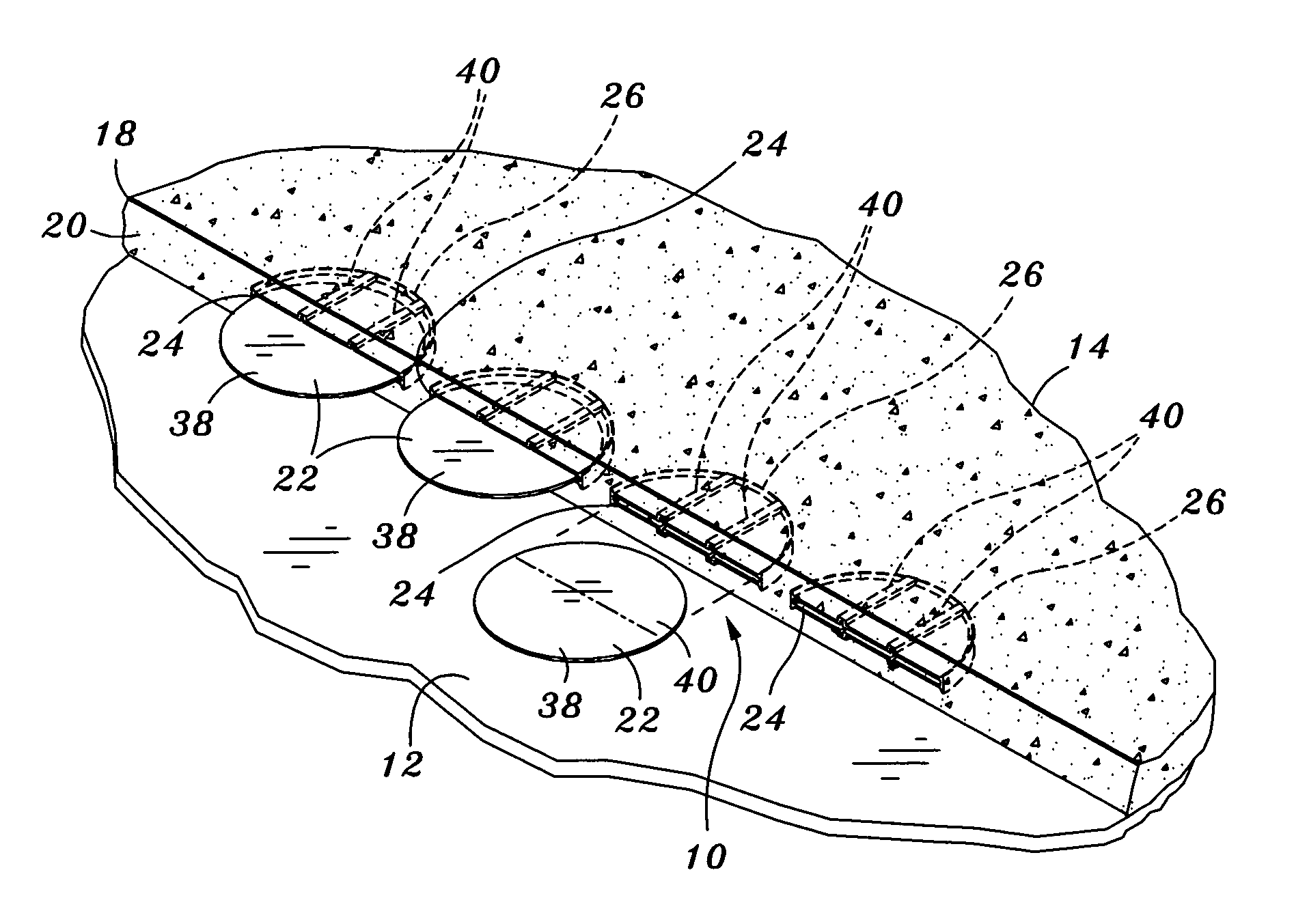
[0030]As can be seen in FIGS. 1 and 2, the disc dowel system 10 is comprised of the dowel plate 22 and the pocket former 26. In FIG. 2, a series of the pocket formers 26 are shown encapsulated in the first pour 14 prior to pouring of the second pour 16. The disc dowel system 10 may further include a positioner bracket 62 for positioning the ...


PUM

PropertyMeasurementUnit
lengthaaaaaaaaaa
widthaaaaaaaaaa
diameteraaaaaaaaaa

Abstract

Disclosed is a disc dowel system interposed between adjacent first and second concrete pours defining a pour joint therebetween. The disc dowel system comprises a positioner bracket, a pocket former and a dowel plate. The positioner bracket has a vertically disposed base flange and a horizontally disposed plate portion extending therefrom. The base flange is rigidly attachable to a concrete form. The pocket former has a horizontally extending interior compartment with an open, generally straight side and an arch-shaped compartment perimeter extending therefrom. The straight side is aligned with the pour joint. The pocket former is positioned within the first pour by the positioner bracket. The dowel plate has a generally rounded shape with an embedded portion and a slidable portion. The embedded portion is rigidly encapsulated within the second pour and the slidable portion is slidably disposed within the pocket former such that the dowel plate permits relative horizontal movement of the first and second pours while restricting relative vertical movement thereof.

Description

CROSS-REFERENCE TO RELATED APPLICATIONS[0001](Not Applicable)STATEMENT RE: FEDERALLY SPONSORED RESEARCH / DEVELOPMENT[0002](Not Applicable)BACKGROUND OF THE INVENTION[0003]The present invention relates generally to concrete forming equipment and, more particularly, to a uniquely configured disc dowel system that is specifically adapted to prevent relative vertical movement of adjacently disposed concrete slabs.[0004]During construction of concrete pavement such as for sidewalks, driveways, roads and flooring in buildings, cracks may occur due to uncontrolled shrinkage or contraction of the concrete. Such cracks are the result of a slight decrease in the overall volume of the concrete as water is lost from the concrete mixture during curing. Typical contraction rates for concrete are about one-sixteenth of an inch for every ten feet of length. Thus, large cracks may develop in concrete where the overall length of the pavement is fairly large. In addition, the cracks may continue to dev...

Claims


Application Information

Patent Timeline
Patent Type & Authority Patents(United States)
IPC IPC(8): E01C11/14E01C11/02
CPCE01C11/14E01C19/504
Inventor SHAW, LEE A.SHAW, RONALD D.
Owner SHAW & SONS
Why Eureka
Try Eureka