
Spacers for ion-exchange device

a technology of spacers and ion exchange devices, which is applied in the direction of cation exchanger materials, membranes, separation processes, etc., can solve the problems of increasing the complexity of the system, increasing the mechanical component, and affecting the sealing effect of the ion exchange devi

Active Publication Date: 2022-07-07
MIS IP HLDG LLC
View PDF7 Cites 3 Cited by
  • Summary
  • Abstract
  • Description
  • Claims
  • Application Information

AI Technical Summary

Benefits of technology

The patent text provides improved spacer borders and methods for fabricating them for ion-exchange devices. These borders can create better external and internal seals, maximizing hydraulic recovery and production rates, while minimizing safety hazards and cross-contamination. Unlike other sealing components, spacing borders are more effective, reliable, and require less component parts. They also require less compression force to seal the device. Additionally, some borders have an internal cavity filled with fabric or mesh, which provides more support to the membranes and ensures more reliable seals throughout the device.

Problems solved by technology

Specifically, many adhesives suitable for sealing an ion-exchange device suffer due to repeated swelling and shrinking of the ion-exchange membranes caused by environmental conditions and water quality.
This swelling and shrinking of an ion-exchange membrane weakens the seal over time and ultimately creates leaks throughout the system.
O-rings inherently add an additional mechanical component and thus an additional degree of complexity.
This additional component and increased complexity can introduce misalignment problems in a membrane stack of an ion-exchange device.

Method used


Image

  • Spacers for ion-exchange device
  • Spacers for ion-exchange device
  • Spacers for ion-exchange device

Examples


Embodiment Construction

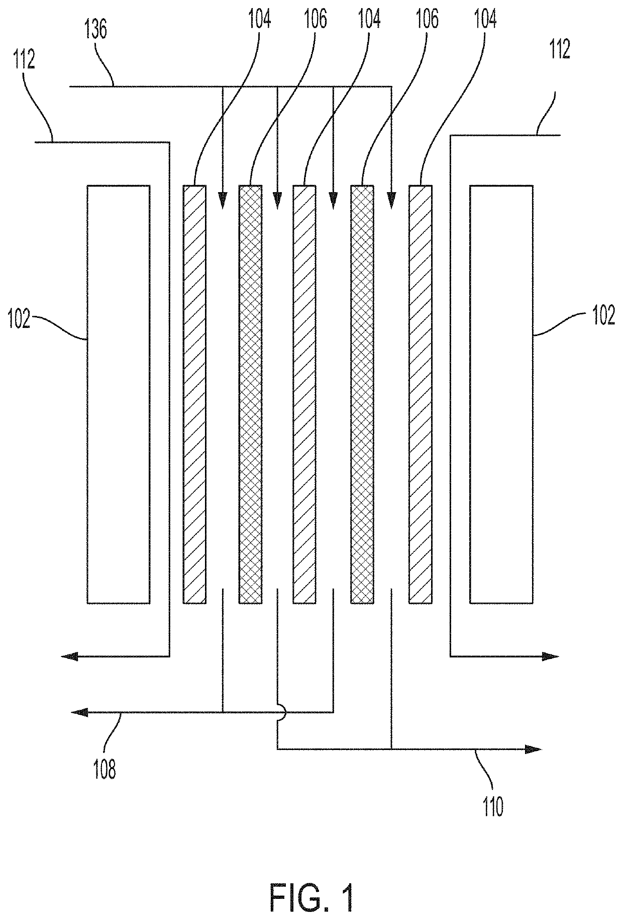
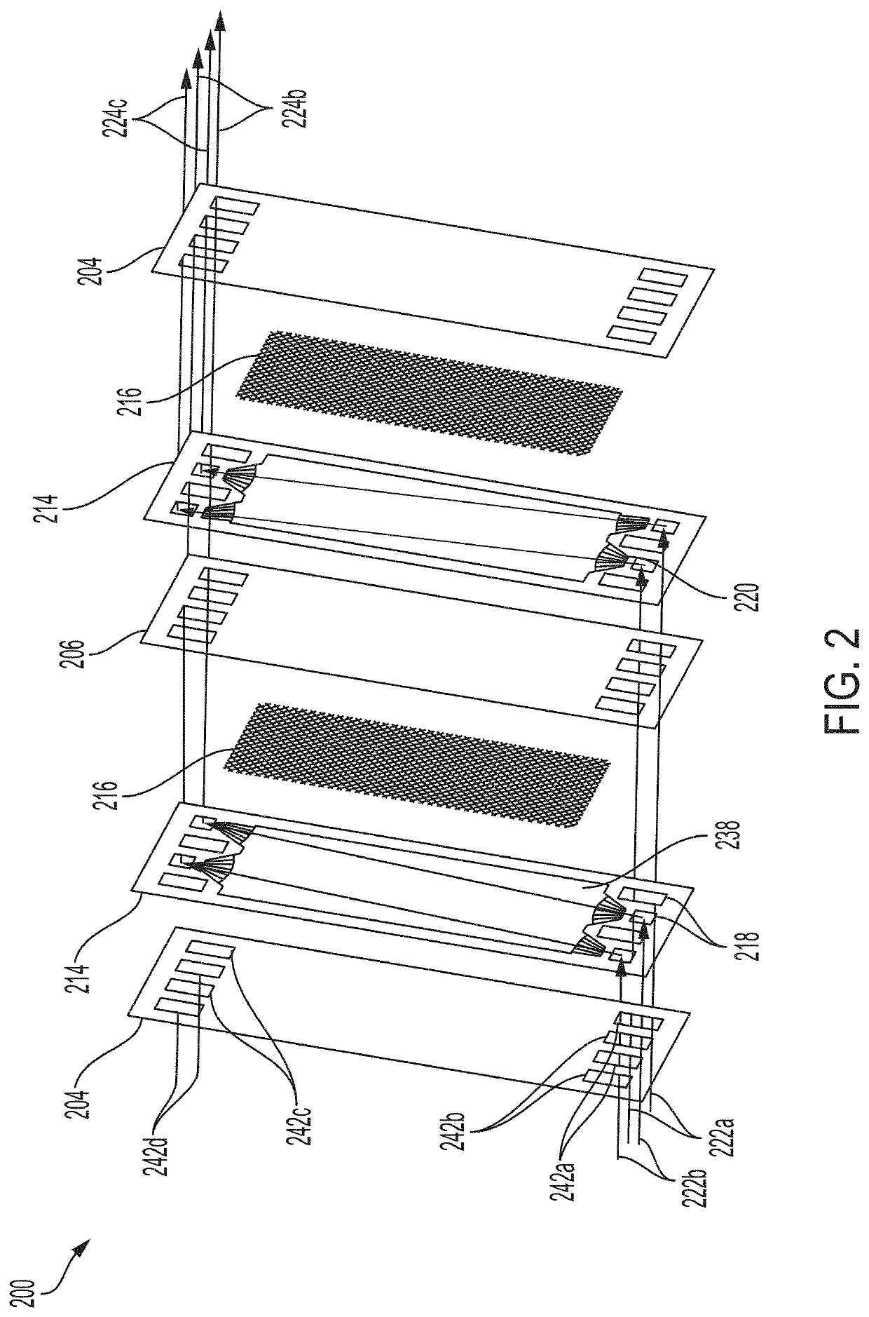
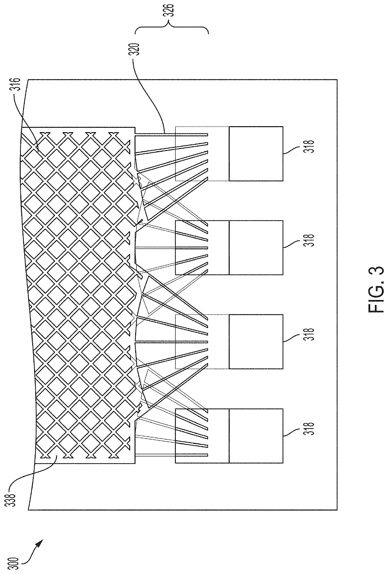
[0055]Described are spacer borders and ion-exchange devices and methods for fabricating spacer borders for use in an ion-exchange device. As described above, the performance of an ion-exchange device relies on the distribution of fluid flow across the ion-exchange membranes of the device, as well as the reliability and effectiveness of the internal seals (i.e., seals between adjacent intermembrane chambers) and external seals (i.e., seals between an interior space and an exterior space of the device) of the device. Poor flow distribution decreases the capacity, production rate, and efficacy of an ion-exchange device. Poor internal seals introduce leaks and cross-contamination from one intermembrane chamber to an adjacent intermembrane chamber. Poor external seals introduce safety hazards, leaks from an interior of the device to an exterior of the device, and contamination from the external environment. Accordingly, embodiments provided herein can improve fluid flow distribution thro...


PUM

PropertyMeasurementUnit
widthaaaaaaaaaa
conductivityaaaaaaaaaa

Abstract

Provided are spacers, ion-exchange devices comprising spacers, and methods of preparing spacers for improved fluid distribution and sealing throughout an ion-exchange device. These spacers can include an internal cavity surrounded by a perimeter of the spacer. The perimeter can have a first opening and a second opening within the perimeter, and the first opening and the second opening can be located on opposite sides of the internal cavity. The spacers can also have a first and second plurality of channels located within the perimeter, wherein each channel of the first and second plurality of channels extends from the internal cavity towards the first opening or the second opening.

Description

REFERENCE TO RELATED APPLICATIONS[0001]This application is a divisional of U.S. application Ser. No. 16 / 685,617, filed Nov. 15, 2019, which claims the benefit of U.S. Provisional Application No. 62 / 768,644, filed Nov. 16, 2018, the entire contents of both of which are incorporated herein by reference.FIELD OF THE DISCLOSURE[0002]This disclosure relates to spacers for a membrane-based desalination device. More particularly, this disclosure relates to spacers for improved flow distribution through an intermembrane chamber and across an ion-exchange membrane of an ion-exchange device, as well as improved external and internal seals of an ion-exchange device.BACKGROUND OF THE DISCLOSURE[0003]Electrodialysis is one example of a membrane-based large scale desalination method. Specifically, electrodialysis can be used in an ion-exchange device to selectively remove positive and negative ions from a water source (e.g., brackish water or brine solution produced in reverse osmosis units) by t...

Claims


Application Information

Patent Timeline
Patent Type & Authority Applications(United States)
IPC IPC(8): B01D15/36B01D61/42B01D65/00B01D61/50
CPCB01D15/361B01D61/50B01D65/003B01D61/422B01D2313/10B01D2313/12B01D2313/20B01D63/085Y02A20/131
Inventor MCDONALD, BRIAN M.CONNOR, JR., MICHAEL JAMES
Owner MIS IP HLDG LLC
Learn More