Display device

a technology of display device and display screen, which is applied in the direction of solid-state devices, semiconductor devices, substation equipment, etc., can solve the problem of reducing the effective area

Pending Publication Date: 2022-06-30
LG DISPLAY CO LTD
View PDF0 Cites 0 Cited by
  • Summary
  • Abstract
  • Description
  • Claims
  • Application Information

AI Technical Summary

Problems solved by technology

However, areas occupied by the disconnection structure and the bypass lines are non-display areas, which can lead to the reduction of an effective area.

Method used


Image

  • Display device
  • Display device
  • Display device

Examples


Embodiment Construction

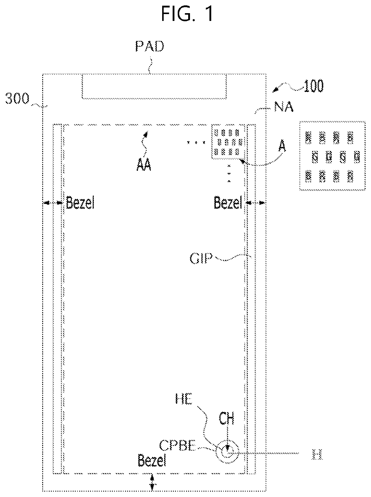
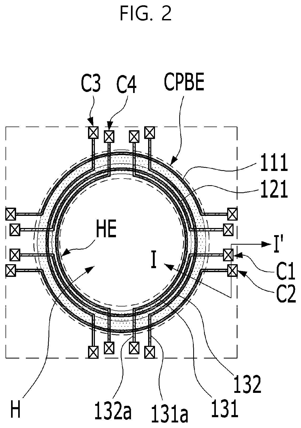
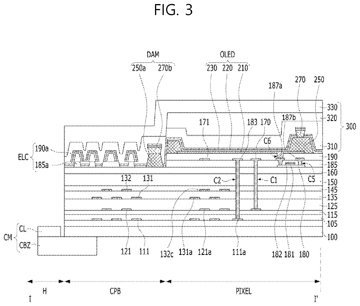
[0021]Reference will now be made in detail to the exemplary embodiments of the present invention, examples of which are illustrated in the accompanying drawings. In the following description of the embodiments and the drawings, the same or similar elements are denoted by the same reference numerals throughout the specification. In the following description of the embodiments of the present invention, a detailed description of known functions and configurations incorporated herein will be omitted when it can make the subject matter of the present invention rather unclear. Further, the names of elements used in the following description of the embodiments of the present invention are selected in consideration of ease of preparation of the specification, and can thus differ from the names of parts of an actual product.

[0022]The shapes, sizes, ratios, angles and numbers of elements given in the drawings to describe the embodiments of the present invention are merely exemplary, and thus,...


PUM

PropertyMeasurementUnit
widthaaaaaaaaaa
areaaaaaaaaaaa
width areaaaaaaaaaaa

Abstract

Discussed is a display device provided with a large effective area by minimizing a margin area around a camera hole in a structure in which the camera hole is formed in a display area. A bypass line module, which is formed in the same process as the process of forming a first thin-film transistor, and a light-emitting device disconnection module, which is formed in the same process as the process of forming a second thin-film transistor, are disposed around the camera hole so as to overlap each other.

Description

CROSS-REFERENCE TO RELATED APPLICATIONS[0001]This application claims priority to Korean Patent Application No. 10-2020-0186848, filed on Dec. 29, 2020 in the Republic of Korea, the entire contents of which are hereby expressly incorporated by reference as if fully set forth herein into the present application.BACKGROUND OF THE INVENTIONField of the Invention[0002]The present invention relates to a display device, and more particularly to a display device provided with a large effective area by minimizing a margin area around a camera hole in a structure in which the camera hole is formed in a display area.Discussion of the Related Art[0003]Recently, an organic light-emitting display device has been considered for a competitive application because it does not require a separate light source and enables realization of a compact device design and vivid color display.[0004]Organic light-emitting display devices are applied to various display devices, such as televisions, smartphones, el...

Claims


Application Information

Patent Timeline
Patent Type & Authority Applications(United States)
IPC IPC(8): H01L27/32H01L51/52H01L51/00
CPCH01L27/3276H01L51/5253H01L51/0096H01L27/3258H01L27/3246H04M1/0266H04M1/0264H10K59/00H10K59/131H01L27/124H01L27/1248H01L27/1225H10K59/65H10K59/124H10K59/1213H10K59/122H10K50/844H10K77/10
Inventor OH, JAE YOUNG
Owner LG DISPLAY CO LTD
Why Eureka
Try Eureka