A shaft top layer arrangement structure of a machine room-less elevator

A machine room-less elevator and shaft technology, which is applied to elevators, lifts, transportation and packaging in buildings, etc., can solve the problems of reducing the effective area of ​​the elevator car, high installation requirements and difficulty, and increasing the top space of the machine room-less, etc. Achieve the effect of saving height and pit depth, maximizing effective area and improving product competitiveness

Active Publication Date: 2016-06-08
GIANT KONE ELEVATOR CO LTD
View PDF5 Cites 0 Cited by
  • Summary
  • Abstract
  • Description
  • Claims
  • Application Information

AI Technical Summary

Problems solved by technology

[0002] The structure of the top floor of the hoistway is very important for machine room-less elevators. It is the most important part related to the rational layout and space optimization of the entire elevator. However, the machine room with large tonnage and high speed has a large volume and takes up a lot of space. , The design of the corresponding main engine bearing platform should be more reliable and firm, and it can carry more weight and force. This will inevitably greatly increase the space on the top floor of the machine room, affect the overall arrangement of the elevator, and affect the area of ​​the car, resulting in waste of space. The effective area of ​​the car is reduced, and at the same time, the complex structure requires high processing technology, and the installation requirements and difficulty are very high. If the deviation angle of the main engine is too large, it is easy to cause the wire rope to fall out of the groove, which is a great safety hazard

Method used


Image

  • A shaft top layer arrangement structure of a machine room-less elevator
  • A shaft top layer arrangement structure of a machine room-less elevator

Examples


Embodiment Construction

[0019] The following specific examples are only explanations of the present invention, and it is not a limitation of the present invention. Those skilled in the art can make modifications without creative contribution to the present embodiment as required after reading this specification, but as long as they are within the rights of the present invention All claims are protected by patent law.

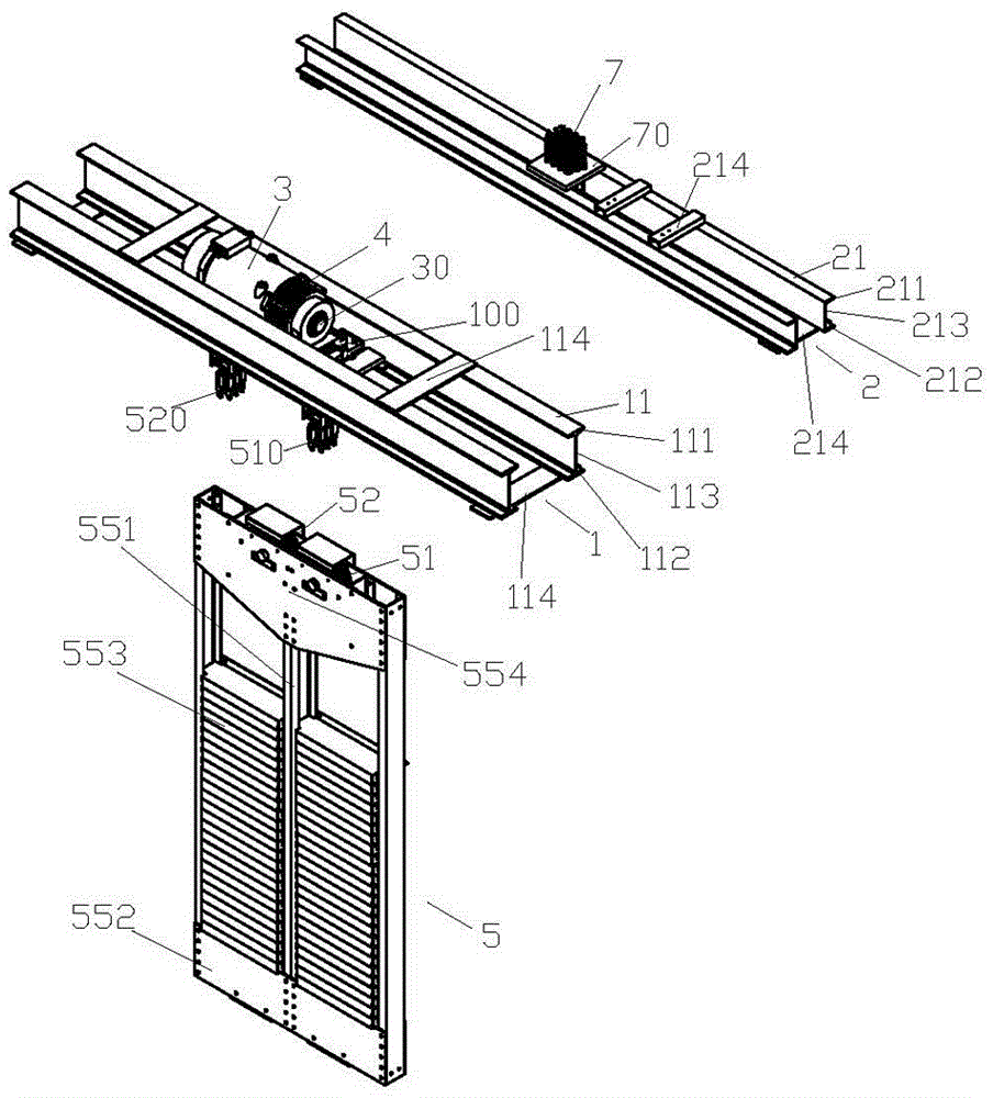
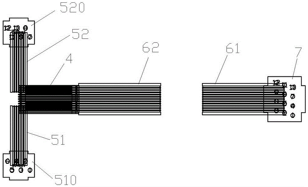
[0020] Examples such as figure 1 , 2 As shown in the figure, a shaft roof arrangement structure of a machine-room-less elevator includes a main beam frame 1 near the rear side wall of the shaft and a sub-frame frame 2 near the front side wall of the shaft arranged in parallel on the top layer of the shaft, and the main beam frame The two ends of 1 and the two ends of the auxiliary beam frame 2 are respectively fixed on the left side wall of the hoistway and the right side wall of the hoistway. The main beam frame 1 includes two main beams 11 arranged in parallel, and the two mai...


PUM


Abstract

The invention relates to the technical field of elevator manufacturing, in particular to an arrangement structure for the shaft top layer of a machine-room-less elevator, including a main girder frame and an auxiliary girder frame. The installation groove, the main installation groove is provided with a horizontal traction drive main engine, the rotating shaft of the horizontal traction driving main engine is parallel to the main beam frame, a traction sheave is connected to the rotating shaft, and a counterweight device is provided under the traction sheave. The weight device is equipped with a left counterweight reversing sheave and a right counterweight reversing sheave, and the main girder is provided with a left counterweight rope end set and a right counterweight rope end set, and the hoistway is located on the front side of the traction wheel In the area on one side of the wall, there are also two front and rear car floor anti-sheaves, which are respectively located on the front and rear sides of the bottom of the car and are used to cooperate with the traction sheave and whose axial direction is parallel to the axial direction of the traction sheave. Just above the front end of the anti-rope pulley on the front car bottom, there is a car rope head group installed on the sub-beam frame. High structural strength, safe and stable operation and can greatly save space.

Description

technical field [0001] The invention relates to the technical field of elevator manufacturing, in particular to a hoistway top layer arrangement structure of a machine room-less elevator. Background technique [0002] The structure of the top floor of the hoistway is very important for machine room-less elevators. It is the most important part related to the rational layout and space optimization of the entire elevator. However, the machine room with large tonnage and high speed has a large volume and takes up a lot of space. , The design of the corresponding main engine bearing platform should be more reliable and firm, and it can carry more weight and force. This will inevitably greatly increase the space on the top floor of the machine room, affect the overall arrangement of the elevator, and affect the area of ​​the car, resulting in waste of space. The effective area of ​​the car is reduced, and at the same time, the complex structure requires high processing technology...

Claims


Application Information

Patent Timeline
Patent Type & Authority Patents(China)
IPC IPC(8): B66B7/00B66B11/04
CPCB66B7/00B66B11/04
Inventor 席超高德炎钱斌
Owner GIANT KONE ELEVATOR CO LTD
Why Eureka
Try Eureka