Modular intramedullary nail

a module and intramedullary technology, applied in the field of modules, can solve the problems of increasing and unnecessary inventory, increasing hospital and patient costs,

Inactive Publication Date: 2005-08-09
SOHNGEN GARY W +1
View PDF36 Cites 79 Cited by
  • Summary
  • Abstract
  • Description
  • Claims
  • Application Information

AI Technical Summary

Benefits of technology

[0009]In accordance with the present invention, depending upon a patient's requirements, by using the various inserts, selected screw configurations can be achieved and chosen preoperatively and then assembled before insertion. Use of multiple inserts with a single nail member allows a surgeon to place screws at various angles and in various locking configurations including antegrade, reconstruction and retrograde along with dynamic oblique locking and dynamic transverse locking.

Problems solved by technology

This results in increased and unnecessary inventory that correspondingly increases the cost to the hospital and patient.

Method used


Image

  • Modular intramedullary nail
  • Modular intramedullary nail
  • Modular intramedullary nail

Examples


Embodiment Construction

)

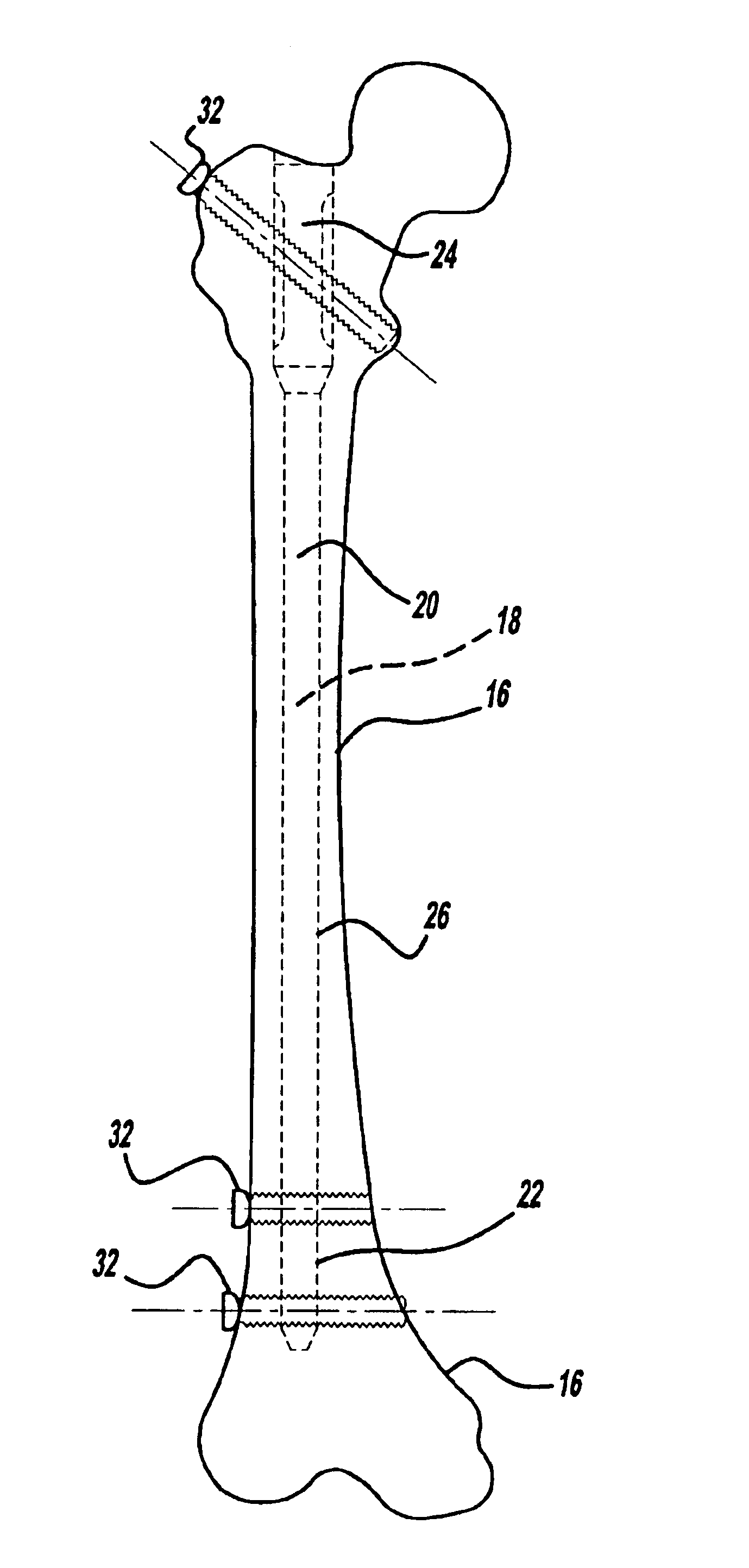
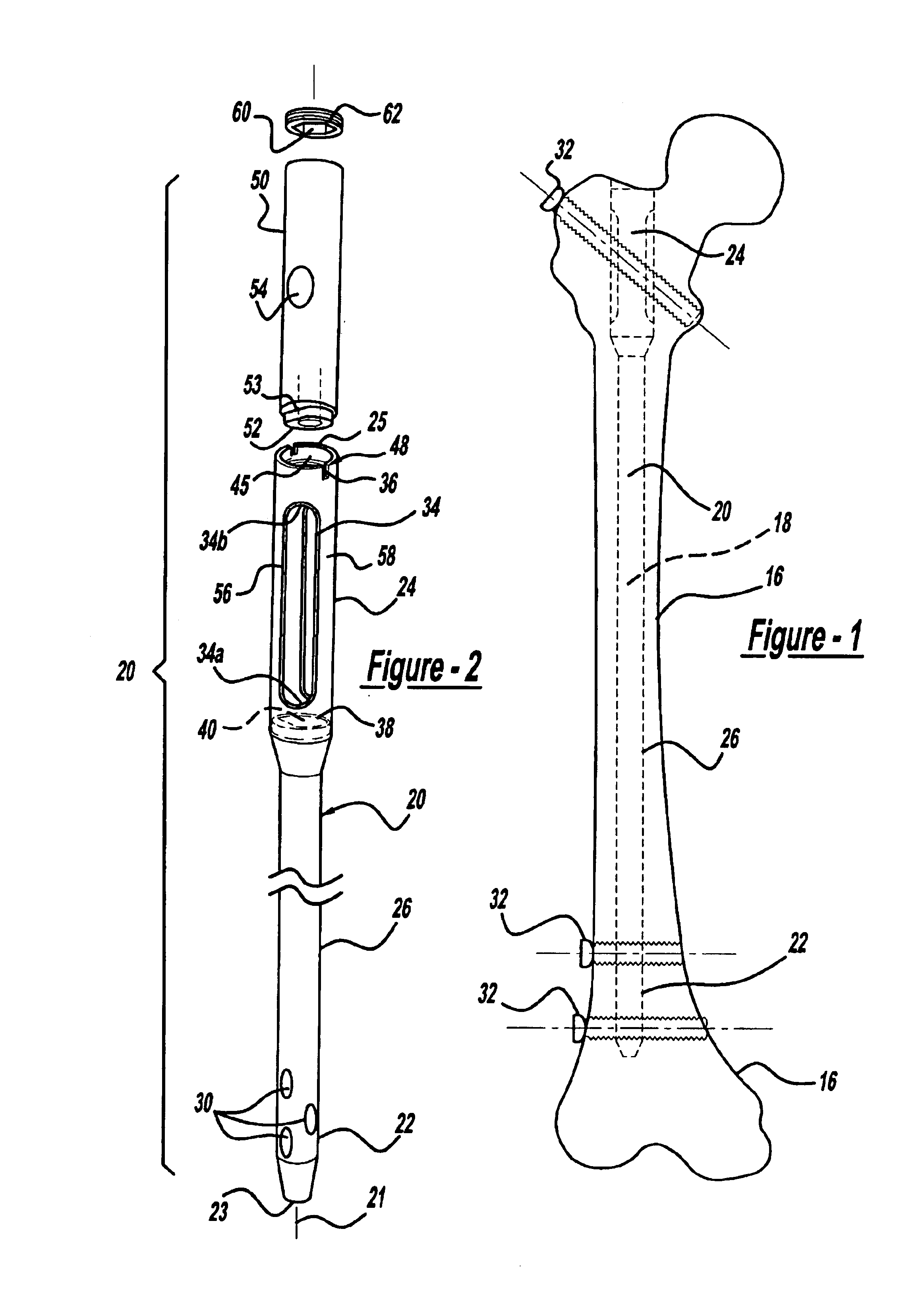
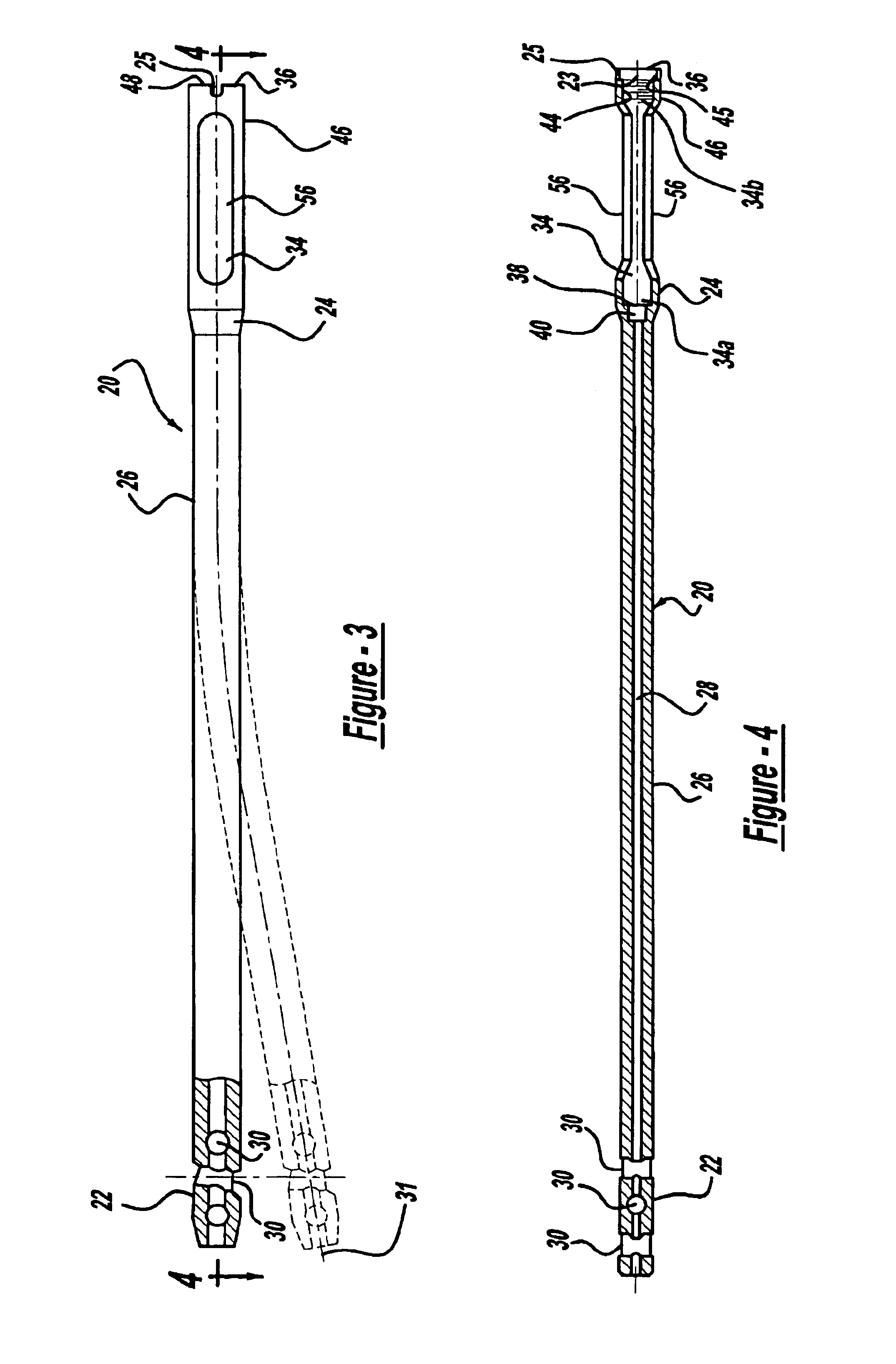
[0036]FIGS. 1-4 shows a modular intramedullary nail 18 according to one embodiment of the present invention placed an assembled condition within a bone 16 bone. The modular intramedullary nail 18 includes a nail member 20 formed of a metallic alloy such as a titanium alloy. The nail member 20 includes a distal end 22, a proximal end 24 and a middle portion 26. The distal end 22 includes a leading edge 23 and the proximal end 24 includes a trailing or rear edge 25. A passageway 28 extends longitudinally through the nail member 20 between the proximal end 24 and the distal end 22. The passageway 28 receives insertion and extraction instrumentation, such as a guidewire (not shown), used to position the nail member 20 within the bone 16. Typically the leading edge 23 of the nail member 20 follows the path of the guide wire and is inserted into the bone 16 first.

[0037]As illustrated in FIG. 1, a plurality of fasteners 32, illustrated herein as bone screws, extend through the nail member...


PUM


Abstract

An intramedullary nail for repair of bone fractures. The intramedullary nail is of a modular configuration including a nail member having a chamber formed on the proximal end thereof. An insert having at least one opening therein for receiving a bone screw or fastener is disposed within the chamber and is secured therein by a locking ring. Accordingly, various inserts may be used to achieve selected bone screw or fastener configurations.

Description

[0001]This is a continuation-in-part of application Ser. No. 09 / 694,666 filed Oct. 23, 2000, now abandoned, and which claims benefit of No. 60 / 160,656 filed Oct. 21, 1999.BACKGROUND OF THE INVENTION[0002]1. Field of the Invention[0003]The present invention relates generally to an intramedullary nail for the repair of bone fractures, and more specifically, to a modular nail that allows a surgeon to use different inserts to achieve a selected nail configuration for use with a particular type of fracture.[0004]2. Description of the Related Art[0005]Intramedullary nails are proven devices that provide a temporary fixation means to stabilize a fracture until the fracture heals. The nail is inserted in the marrow canal of the bone and is positioned to span the fracture. The nail is received and anchored within the bone via bone screws placed through aligned apertures in the nail.[0006]The screws are usually inserted in the proximal and distal ends of the nail and in the case of the proxim...

Claims


Application Information

Patent Timeline
Patent Type & Authority Patents(United States)
IPC IPC(8): A61B17/72A61B17/68A61B17/78A61B17/00
CPCA61B17/68A61B17/72A61B17/7233A61B17/7241A61B17/744A61B2017/00004
Inventor SOHNGEN, GARY W.RUSH, BRYAN J.
Owner SOHNGEN GARY W
Why Eureka
Try Eureka