
Palm scanner using a programmable nutating mirror for increased resolution

a technology of a nutating mirror and a palm scanner, which is applied in the field of palm print imaging systems, can solve the problem of not being able to provide palm images at 500 dots per inch (dpi) resolution using a single camera, and achieve the effect of increasing resolution

Active Publication Date: 2005-08-09
HID GLOBAL CORP
View PDF200 Cites 42 Cited by
  • Summary
  • Abstract
  • Description
  • Claims
  • Application Information

AI Technical Summary

Benefits of technology

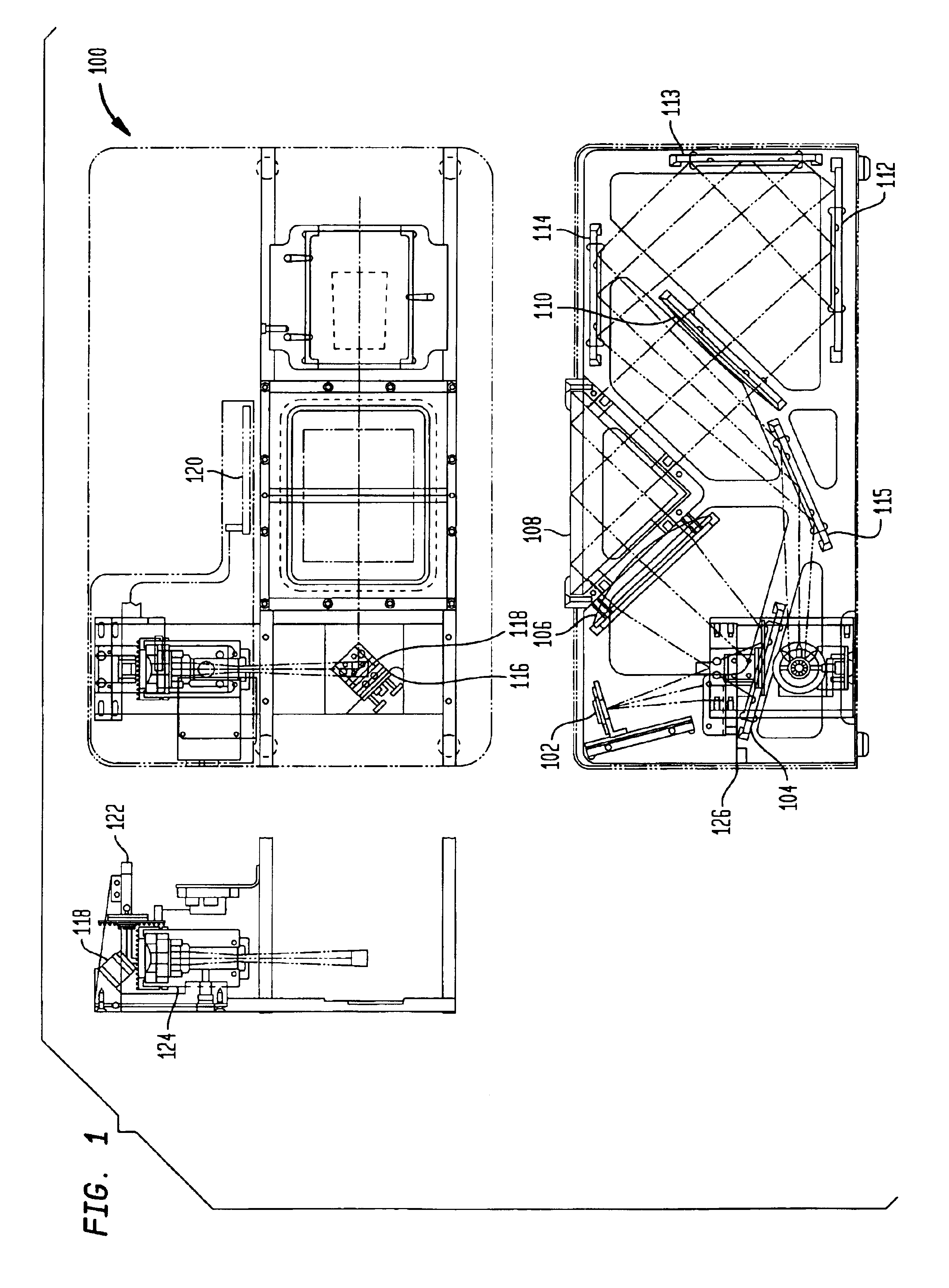
[0009]The present invention solves the above mentioned needs by providing a palm scanner that captures palm images at a high resolution (at least 500 dpi or greater) using a single camera. The present invention accomplishes this by including a two dimensional programmable nutating mirror that increases the resolution provided by a single camera.

Problems solved by technology

However, due to the curvature of the palm and insufficient contact between the palm and a flat platen, conventional palm imaging systems usually provide a scanned image of the palm that includes blank pockets representative of the curvature of the palm.
Another problem with existing palm scanners is the inability to provide palm images at 500 dots per inch (dpi) resolution using a single camera.

Method used


Image

  • Palm scanner using a programmable nutating mirror for increased resolution
  • Palm scanner using a programmable nutating mirror for increased resolution
  • Palm scanner using a programmable nutating mirror for increased resolution

Examples


Embodiment Construction

[0018]While the present invention is described herein with reference to illustrative embodiments for particular applications, it should be understood that the invention is not limited thereto. Those skilled in the art with access to the teachings provided herein will recognize additional modifications, applications, and embodiments within the scope thereof and additional fields in which the present invention would be of significant utility.

Overview

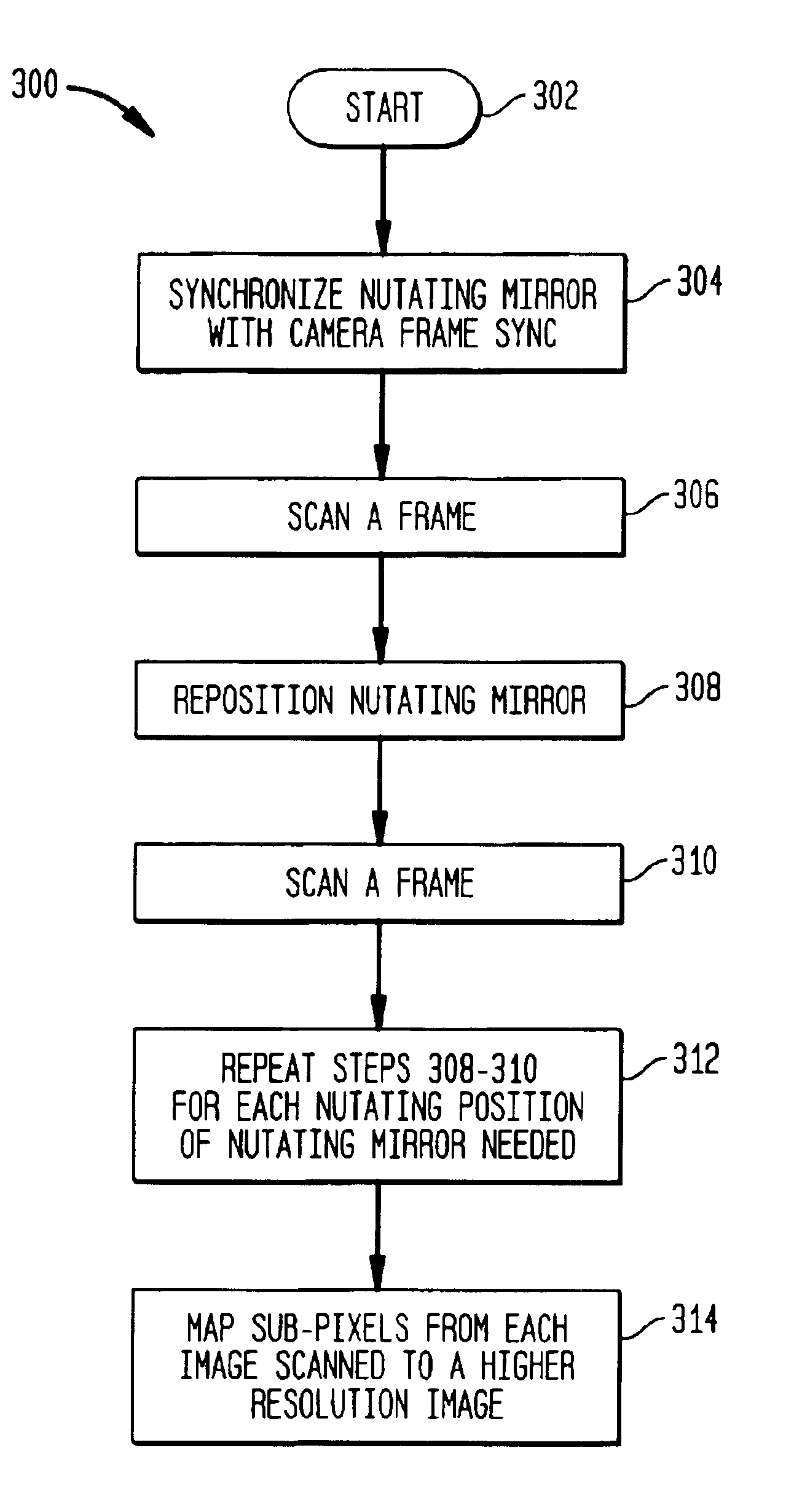
[0019]The present invention is a palm print scanner and method for increasing image resolution using a single camera. The camera (capable of providing images at 250 dpi) and a nutating mirror enable the present invention to provide a method of increasing image resolution to 500 dpi or more. The present invention also supports palm and writer's palm (hypothenar) print images.

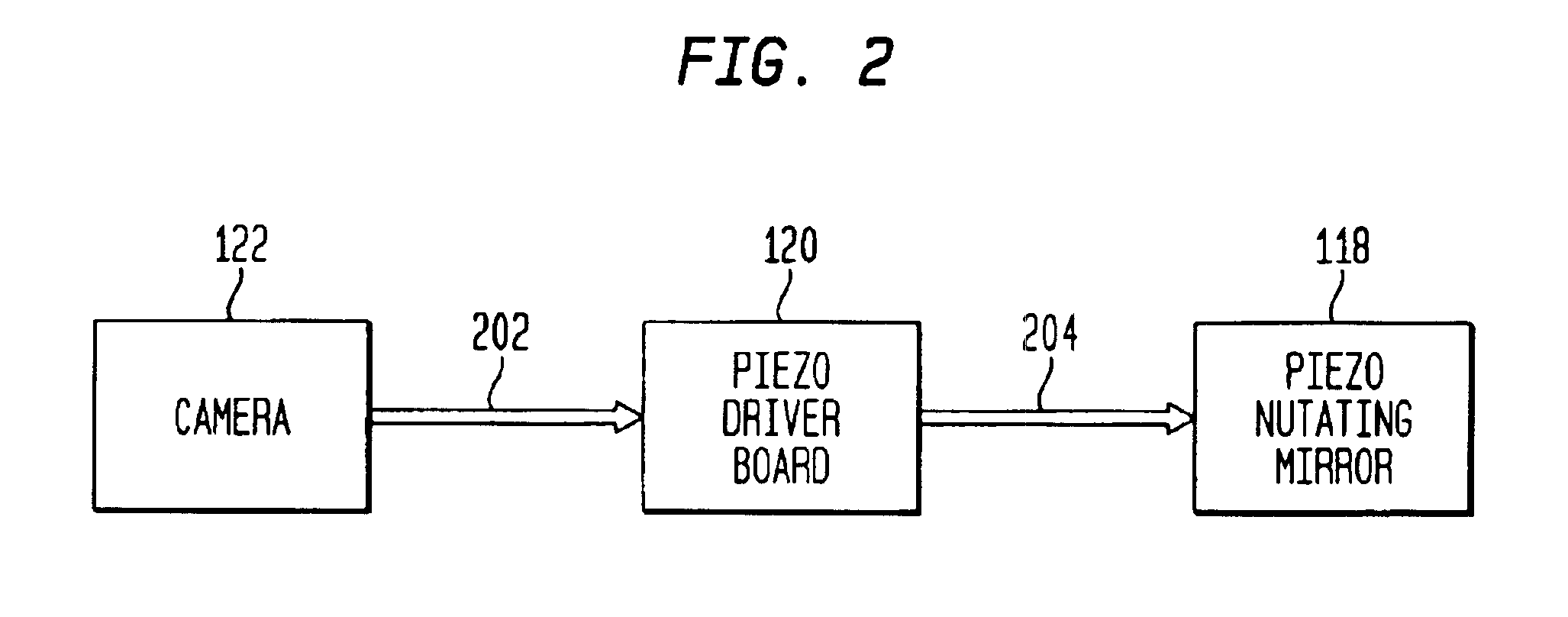
[0020]FIG. 1 is a block diagram of a palm print scanner 100 according to an embodiment of the present invention. Palm print scanner 100 comprises, inter alia, an LED il...


PUM


Abstract

A system and method for increasing image resolution in a palm print scanner. The method of the invention requires the synchronization of a nutating mirror with a camera frame sync. A first image is scanned at a first nutation position. The mirror is nutated by a fraction of a pixel amount in one direction. Another image is scanned at a second nutation position. The process of nutating the mirror to a different nutation position and scanning an image is repeated until all sub-pixels needed to increase an image resolution are obtained. All of the sub-pixels obtained are then interlaced to obtain a higher resolution image.

Description

[0001]This application claims the benefit under 35 U.S.C. §119(e) of U.S. Provisional Application No. 60 / 255,890, filed Dec. 18, 2000, which is incorporated by reference herein in its entirety.BACKGROUND OF THE INVENTION[0002]1. Field of the Invention[0003]The present invention is generally directed to palm print imaging systems.[0004]2. Related Art[0005]Biometrics is a science involving the analysis of biological characteristics. Biometric imaging captures a measurable characteristic of a human being for identity purposes. See, e.g., Gary Roethenbaugh, Biometrics Explained, International Computer Security Association, Inc., pp. 1-34, (1998), which is incorporated herein by reference in its entirety.[0006]One type of biometric imaging system is an Automatic Fingerprint Identification System (AFIS). Automatic Fingerprint Identification Systems are used for law enforcement purposes. Law enforcement personnel collect fingerprint images from criminal suspects when they are arrested. Law...

Claims


Application Information

Patent Timeline
IPC IPC(8): G06K9/00
CPCG06K9/00046G06V40/1324
Inventor SCOTT, WALTER G.VAN DUSEN, JOHNIRVING, RICHARD D.
Owner HID GLOBAL CORP
Learn More