Combination of a press brake clamping system and at least a press brake tool

a technology of press brake and clamping system, which is applied in the direction of metal-working tools, shaping tools, manufacturing tools, etc., can solve the problems of tools being damaged, tools being generally heavy, and aligning and bringing to abutment cannot be done by hand

Inactive Publication Date: 2005-08-16
WILA
View PDF30 Cites 43 Cited by
  • Summary
  • Abstract
  • Description
  • Claims
  • Application Information

AI Technical Summary

Benefits of technology

[0032]a safety tang to prevent the t...

Problems solved by technology

As the tools are generally very heavy, this aligning and bringing to abutment can not be done by hand.
This method of arranging the upper tool into the upper beam is time consuming and ...

Method used


Image

  • Combination of a press brake clamping system and at least a press brake tool
  • Combination of a press brake clamping system and at least a press brake tool
  • Combination of a press brake clamping system and at least a press brake tool

Examples


Embodiment Construction

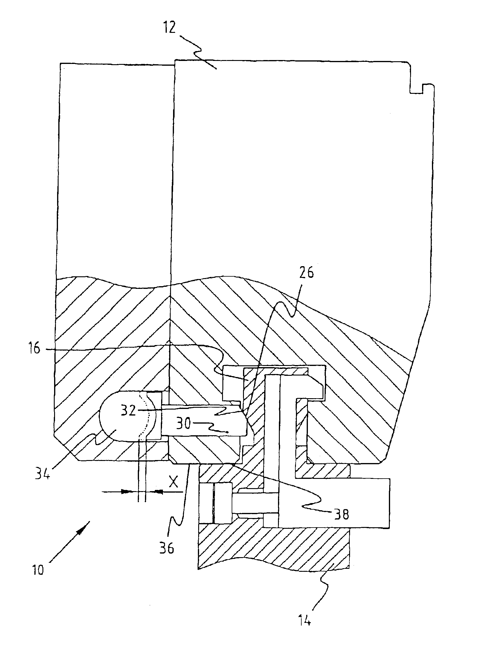
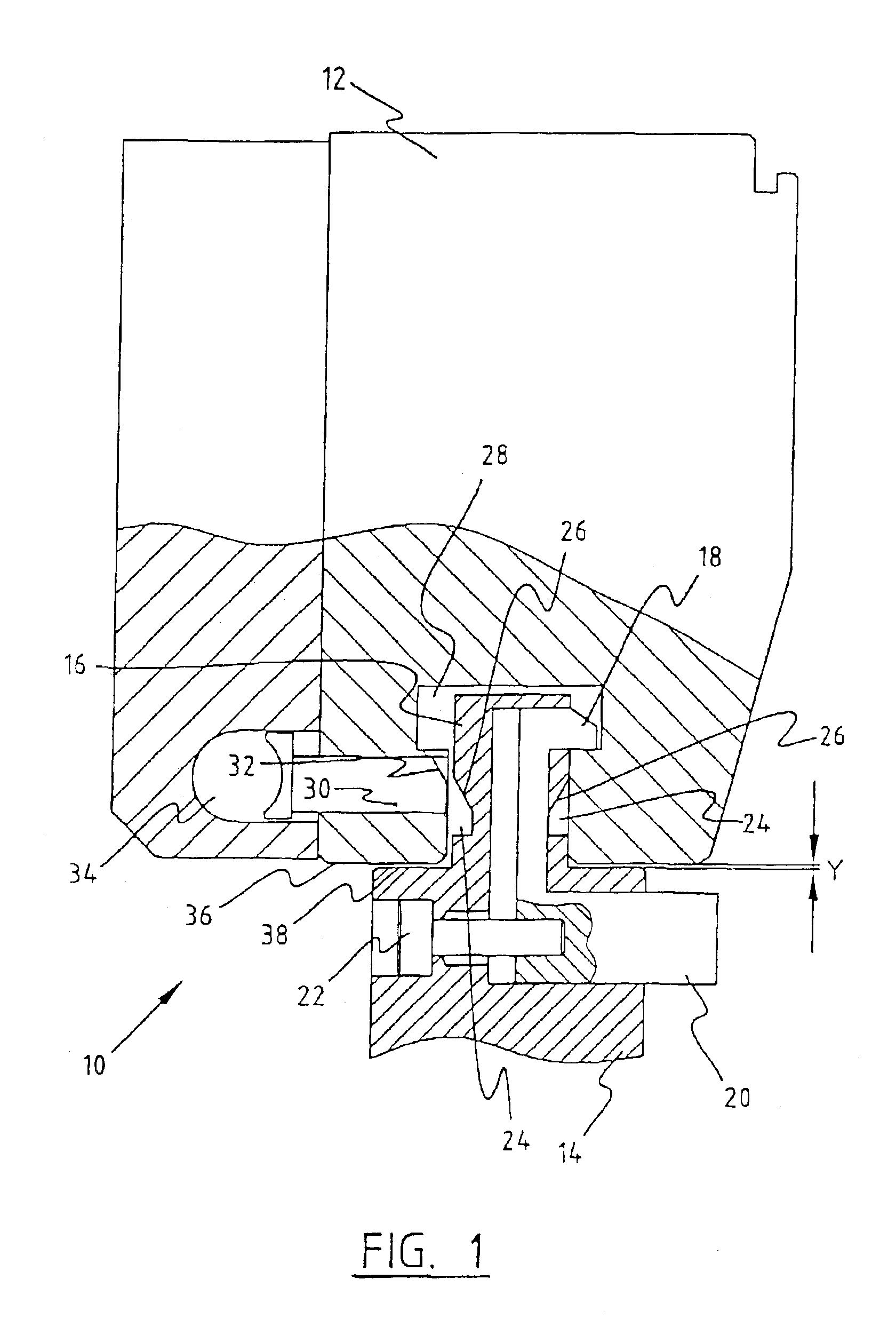
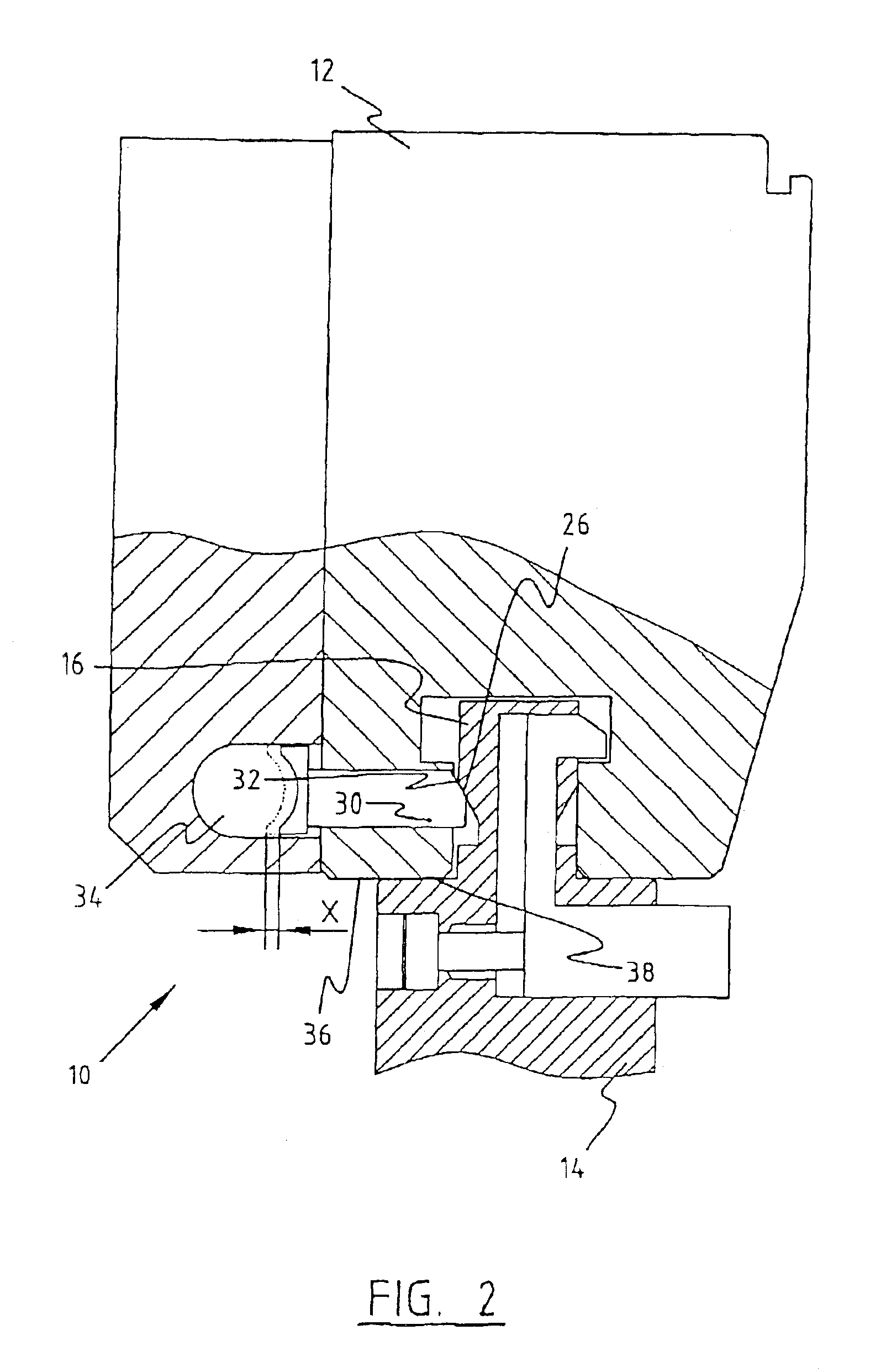
[0037]FIG. 1 shows a first preferred embodiment 10 according to the invention. This combination 10 comprises a clamping system 12 and a tool 14. The tool 14 is generally shaped as an American style tool. It has a clamping part 16 and a safety tang 18. This safety tang 18 is retractable and operable by a push button 20, which extends from the tool body. The end position of the push button 20 is defined by a bolt 22, which is arranged into the back of the push button 20.

[0038]The clamping part 16 comprises two recesses 24, each with a slanting end surface 26.

[0039]The clamping system 12 comprises a groove 28 with a T-shaped cross section. Furthermore a horizontal pin 30 is movable and extends into the groove 28. The pin 30 has an end surface 32 which is partially slanted. The pin 30 is movable by a bellow 34, which is operable by for example pressurized air.

[0040]When the tool 14 is slid into the clamping system 12, the safety tang 18 prevents the tool 14 from falling out. However, th...


PUM

PropertyMeasurementUnit
Forceaaaaaaaaaa
Safety-related propertiesaaaaaaaaaa

Abstract

The invention relates to a combination of a press brake tool and a press brake clamping system for pressing the press brake tool in a press direction, said press brake clamping system comprising:
    • at least one clamp for clamping said tool in a clamping direction substantially perpendicular to the press direction;
    • a positioner for positioning said tool in the press direction; and
    • at least one tool support surface;
said tool comprising:
  • a tool body;
  • a clamping part arranged on said tool body for clamping said tool in said clamping system, wherein the clamping part has an engagement part for engagement of the positioner onto the tool;
  • at least one support surface for abutment to said tool support surface; and
  • a safety tang to prevent the tool of falling out;
  • wherein at least one of the positioner and the engagement part comprises a slanting surface for at least partially transforming the clamping force into a positioning force.

    Description

    FIELD OF THE INVENTION[0001]The invention relates to a combination of a press brake clamping system and at least a press brake tool, which is commonly known as “American-style” tooling.BACKGROUND OF THE INVENTION[0002]A press brake has a massive table on which at least two robust C-frames are arranged. On the topside an upper beam is arranged between the C-frames. A bottom tool (the die) is arranged on the table or lower beam and a top tool (the punch) is arranged on the upper beam. The upper and lower beam are movable relatively to each other. The upper beam is generally movable by two synchronised hydraulic cylinders which move the top tool and the bottom tool towards each other and from each other. By placing a workpiece between the two tools, it is possible to bend the workpiece with such a press brake. At least the upper tools are arranged in a clamping system to clamp the tools and prevent them from shifting when the press brake is used or even to prevent falling out of the to...

    Claims


    Application Information

    Patent Timeline
    IPC IPC(8): B21D5/02
    CPCB21D5/0209B21D5/0236
    Inventor ENDERINK, ALBERT
    Owner WILA
    Why Eureka
    Try Eureka