Coaxial connector structure

a technology of connectors and connectors, applied in the direction of coupling devices, two-part coupling devices, electrical devices, etc., can solve the problems of affecting the quality of signal transmission and receiving, time and labor consumption, complicated and labor-intensive hours, etc., and achieves the effect of simple design, more reliable, and production in automation

Inactive Publication Date: 2005-08-16
HUANG LIANG PRECISION ENTERPRISE
View PDF5 Cites 25 Cited by
  • Summary
  • Abstract
  • Description
  • Claims
  • Application Information

AI Technical Summary

Benefits of technology

[0006]It is the primary object of the present invention to provide a coaxial connector structure, which design is simple and can be produced in automation.
[0007]It is another object of the present invention to provide a coaxial connector structure, which is more reliable.
[0008]It is a further object of the present invention to provide a coaxial connector structure, which provides a better connection signal.
[0009]It is still a further object of the present invention to provide a coaxial connector structure, which saves labor hours and is cost effectiveness.

Problems solved by technology

However, the connection between the connecting section A2 and the signal wire B is not strong enough that can easily be detached by force, and the peering away of the metal layer B3 has to be done manually, which consumes time and labor.
This design is complicated and requires more labor hours, and the connecting area is weak and may easily be loosened, which affects the quality of signal transmission and receiving.

Method used


Image

  • Coaxial connector structure
  • Coaxial connector structure
  • Coaxial connector structure

Examples


Embodiment Construction

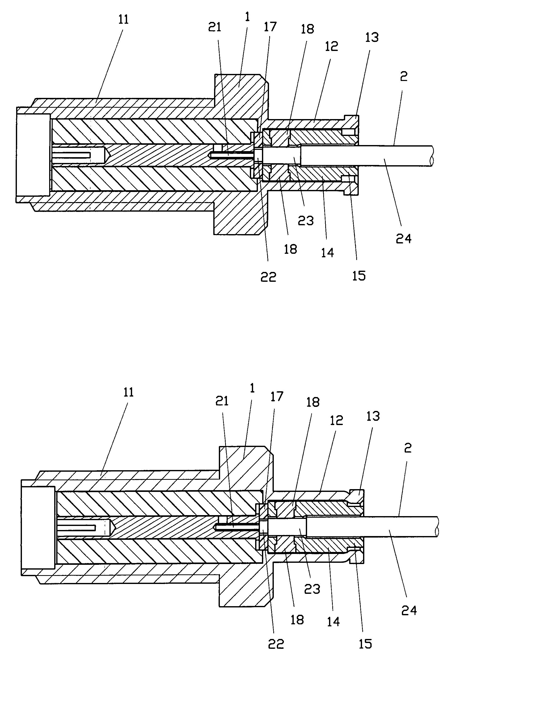
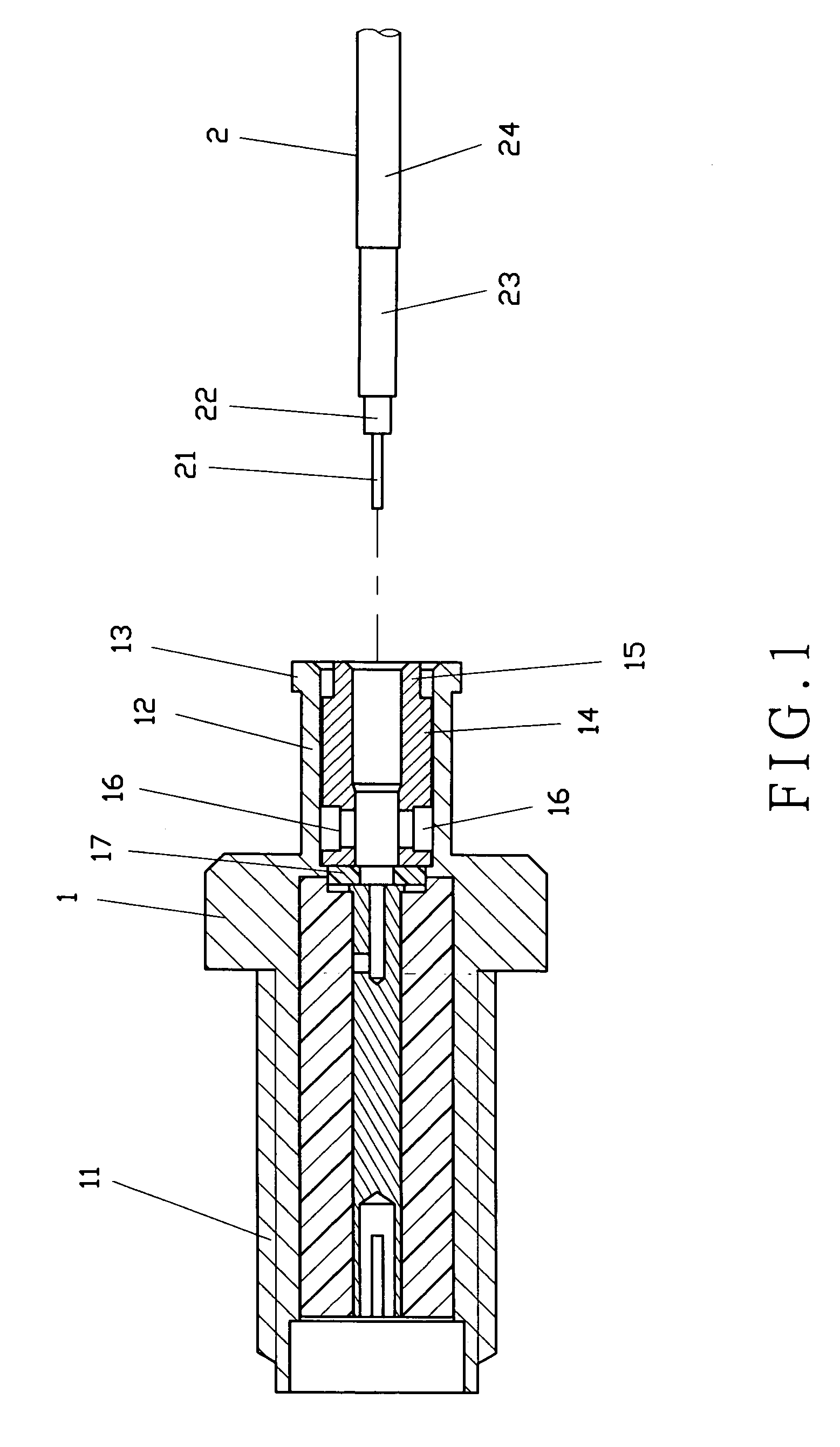
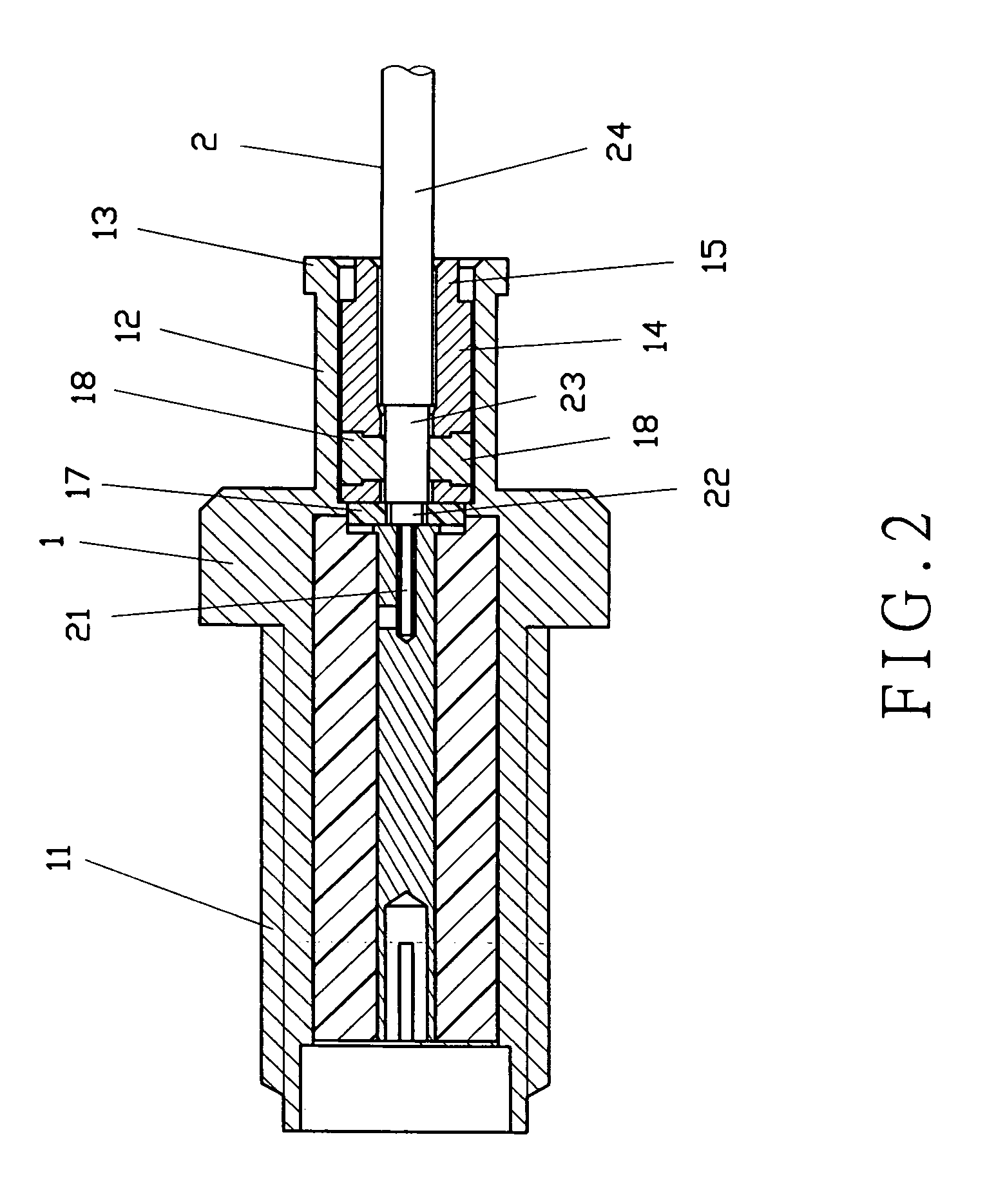
[0015]As shown in FIGS. 1 and 2, the present invention comprises a connector 1 and a signal wire 2.

[0016]The connector 1 is made of metal with one end formed with a threaded section 11 and a hollow connecting section 12 at the opposite end thereof. The connecting section 12 has an enlarged section 13 with a metal sleeve 14 therein. The sleeve 14 is formed with a connecting end 15 at one end and a pair of through holes 16 across the sleeve 14. There is a washer 17 located between the threaded section 11 and the connecting section 12 as an insulating device.

[0017]The signal wire 2 is secured in the connecting section 12 of the connector 1, with a metal core 21 to conduct an electrical pole (either positive or negative pole). The metal core 21 is enwrapped with an insulating layer 22. The insulating layer 22 is enwrapped with a metal layer 23. The metal layer 23 is then protected with a nonconducting cover 24. The metal layer 23 is to conduct another electrical pole (either positive or...


PUM


Abstract

A coaxial connector structure includes a connector and a signal wire. The connector has a threaded section at one end and a connecting section at the opposite end. The connecting section has an enlarged section with a metal sleeve therein. The sleeve is formed with a connecting end at one end and a pair of through holes across the sleeve. The through holes are filled with solder to secure and connect the signal wire with a metal layer to reinforce the strength of the connection between the signal wire and the metal layer.

Description

FIELD OF THE INVENTION[0001]This invention relates to a coaxial connector structure, and more particularly to one using solder to enhance the connection strength and mass production.BACKGROUND OF THE INVENTION[0002]Due to the technology, many products, such as computer, notebook, PDA or many other electric products utilize a coaxial wire to transmit a signal in a fast speed. The coaxial wire requires a coaxial connector to connect products. A conventional one, as shown in FIGS. 4 and 5, comprises a connector A and a signal wire B. The connector A has a threaded section A1 and a connecting section A2 at the other end for the signal wire B to insert therein. There is a washer A3 between the threaded section A1 and the connecting section A2 as an insulator. The connecting section A2 further comprises a sleeve A4 therein. The signal wire B comprises a core B1 to transmit a signal (either a positive or negative pole). The core B1 is enwrapped with an insulating layer B2 which then is enw...

Claims


Application Information

Patent Timeline
Patent Type & Authority Patents(United States)
IPC IPC(8): H01R13/646H01R13/00
CPCH01R24/40H01R2103/00
Inventor LIN, KUOTUNG
Owner HUANG LIANG PRECISION ENTERPRISE
Why Eureka
Try Eureka