Safety syringe cylinder

Inactive Publication Date: 2005-08-16
CHIAN LAI WEN
View PDF3 Cites 261 Cited by
  • Summary
  • Abstract
  • Description
  • Claims
  • Application Information

AI Technical Summary

Benefits of technology

[0010]Accordingly, the primary object of the present invention is to provide a safety syringe cylinder having a structure for attaching a syringe needle precisely. The syringe needle can be retracted into the syringe cylinder for bending. A hook seat is formed at a lower end of the need

Problems solved by technology

The operation i

Method used


Image

  • Safety syringe cylinder
  • Safety syringe cylinder
  • Safety syringe cylinder

Examples


Embodiment Construction

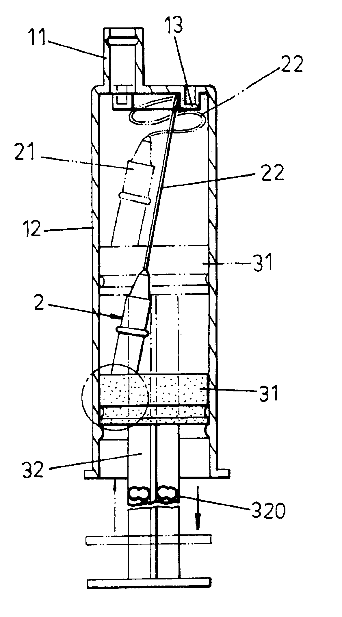
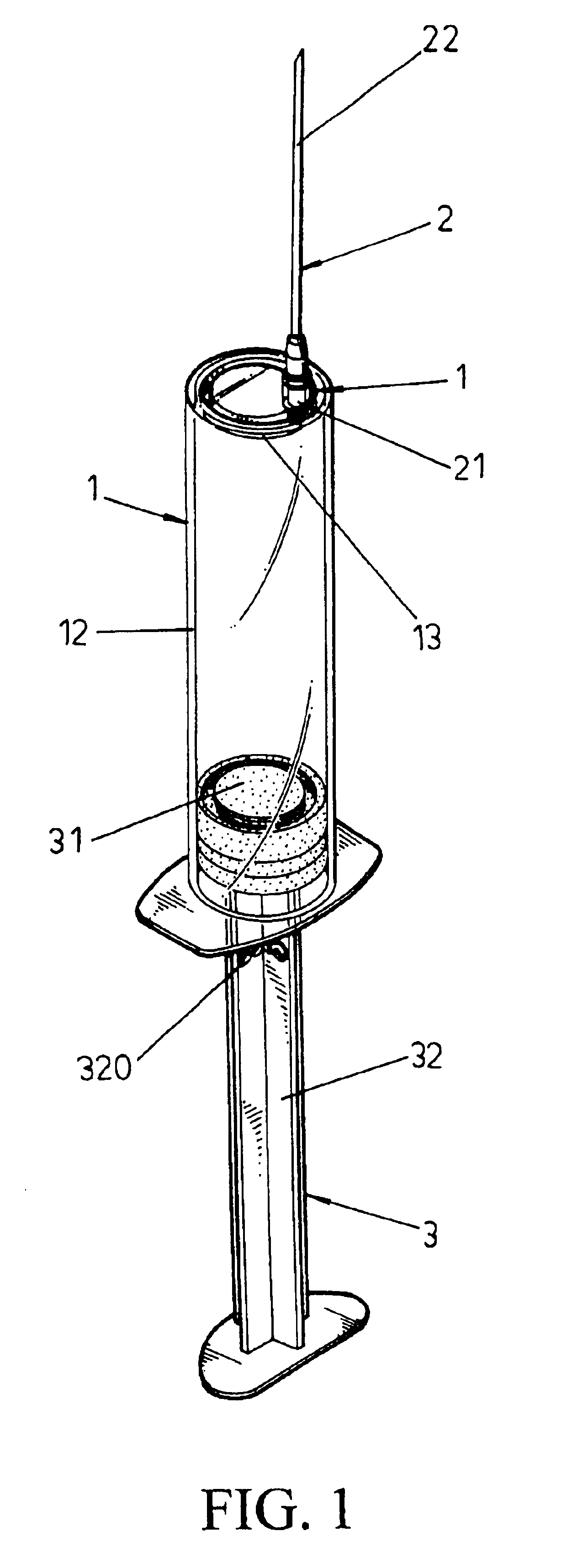
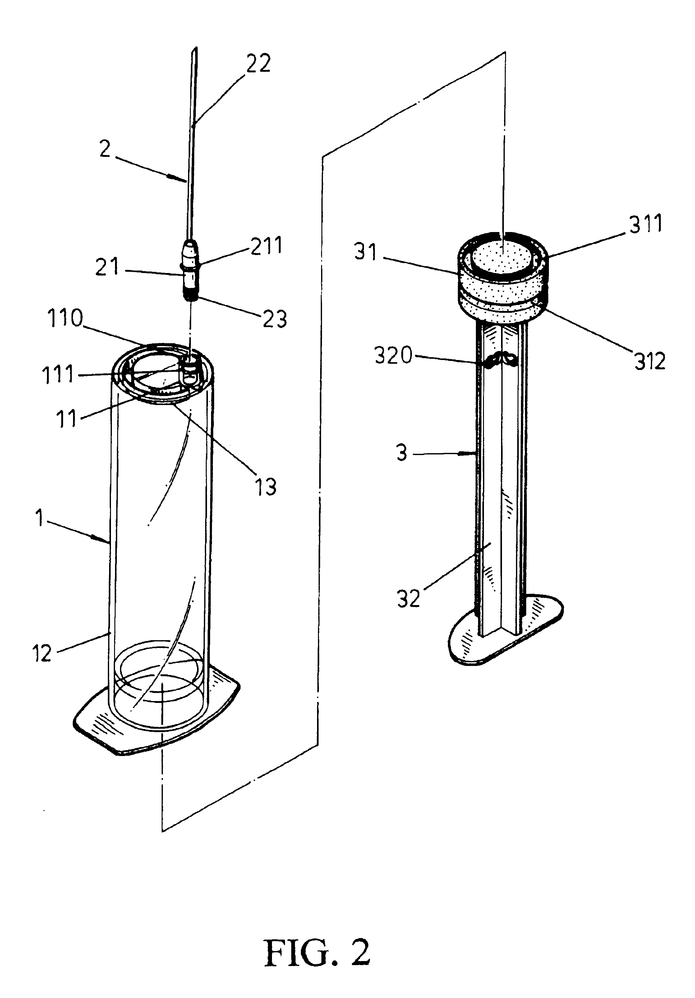
[0024]Referring to FIGS. 1 and 2, the safety syringe cylinder of the present invention is illustrated. The safety syringe cylinder includes a syringe cylinder 1, a syringe needle 2, a push rod 3 and others.

[0025]The upper end of the syringe cylinder 1 has a syringe connecting seat 11. The syringe connecting seat 11 has a positioning groove 111. The inner upper end of the syringe cylinder 1 is installed with an annular ring 13. The lower end of the cylinder body 12 has a cylindrical ring 121.

[0026]An upper end of the syringe needle 2 is a needle tube 22 and the lower end is a needle 21. A periphery of the needle 21 has a protruding ring 211 and a lower end of the needle 21 has a hook seat 23. Two wedge rings 231 are arranged around the needle 21. A center of the hook seat 23 is a channel hole 230. The channel hole 230 penetrates through the needle 21 so as to communicate to the needle tube 22. The hook seat 23 is installed with a guide hole 232, as shown in the FIGS. 3 and 4.

[0027]A ...


PUM


Abstract

A safety syringe cylinder has a structure for attaching a syringe needle precisely. The syringe needle can be retracted into the syringe cylinder for bending. A hook seat is formed at a lower end of the needle. An annular hook groove is formed at a top end of the push rod cap. The hook seat is engaged with the annular hook groove so as to control the displacement and bending process of the syringe needle. Thereby, the processing of undesired syringe needle is safe, reliable and convenient.

Description

FIELD OF THE INVENTION[0001]The present invention relates to medical devices, and particularly to a safety syringe cylinder having a structure for attaching a syringe needle precisely and the processing of undesired syringe needle is safe, reliable and convenient.BACKGROUND OF THE INVENTION[0002]Subcutaneous injections are frequently used in the medical treatment. Retractable safety syringe injectors are especially suitable for subcutaneous injection, which has the following advantages:[0003]1. The retractable safety syringe cylinder is safe and retractable so as not to hurt anybody.[0004]2. The retractable safety syringe cylinder has a self-destroy function. If an overlarge force is used to break the syringe cylinder, the needle will not be ejected out.[0005]3. It is disposable after used once.[0006]4. The use of the retractable safety syringe cylinder is similar to the conventional injector, it can be operated by a simple training.[0007]FIG. 12 shows the structure of a retractable...

Claims


Application Information

Patent Timeline
IPC IPC(8): A61M5/32A61M5/34A61M5/50
CPCA61M5/322A61M5/5066A61M2005/3223A61M2005/342
Inventor CHIAN, LAI-WEN
Owner CHIAN LAI WEN
Why Eureka
Try Eureka