Rotary electric machine stator and method of manufacturing the same

a technology of rotary electric machines and stators, which is applied in the manufacture of winding connections, windings, dynamo-electric components, etc., can solve the problem of increasing the useless axial size of the stator

Inactive Publication Date: 2005-08-16
DENSO CORP
View PDF21 Cites 13 Cited by
  • Summary
  • Abstract
  • Description
  • Claims
  • Application Information

AI Technical Summary

Problems solved by technology

When a stator is manufactured by the above-described method, the connection ends 406 have to have ...

Method used


Image

  • Rotary electric machine stator and method of manufacturing the same
  • Rotary electric machine stator and method of manufacturing the same
  • Rotary electric machine stator and method of manufacturing the same

Examples


Embodiment Construction

[0030]A method of manufacturing stator winding of a rotary electric machine stator according to a preferred embodiment of the invention will be described with reference to the appended drawings.

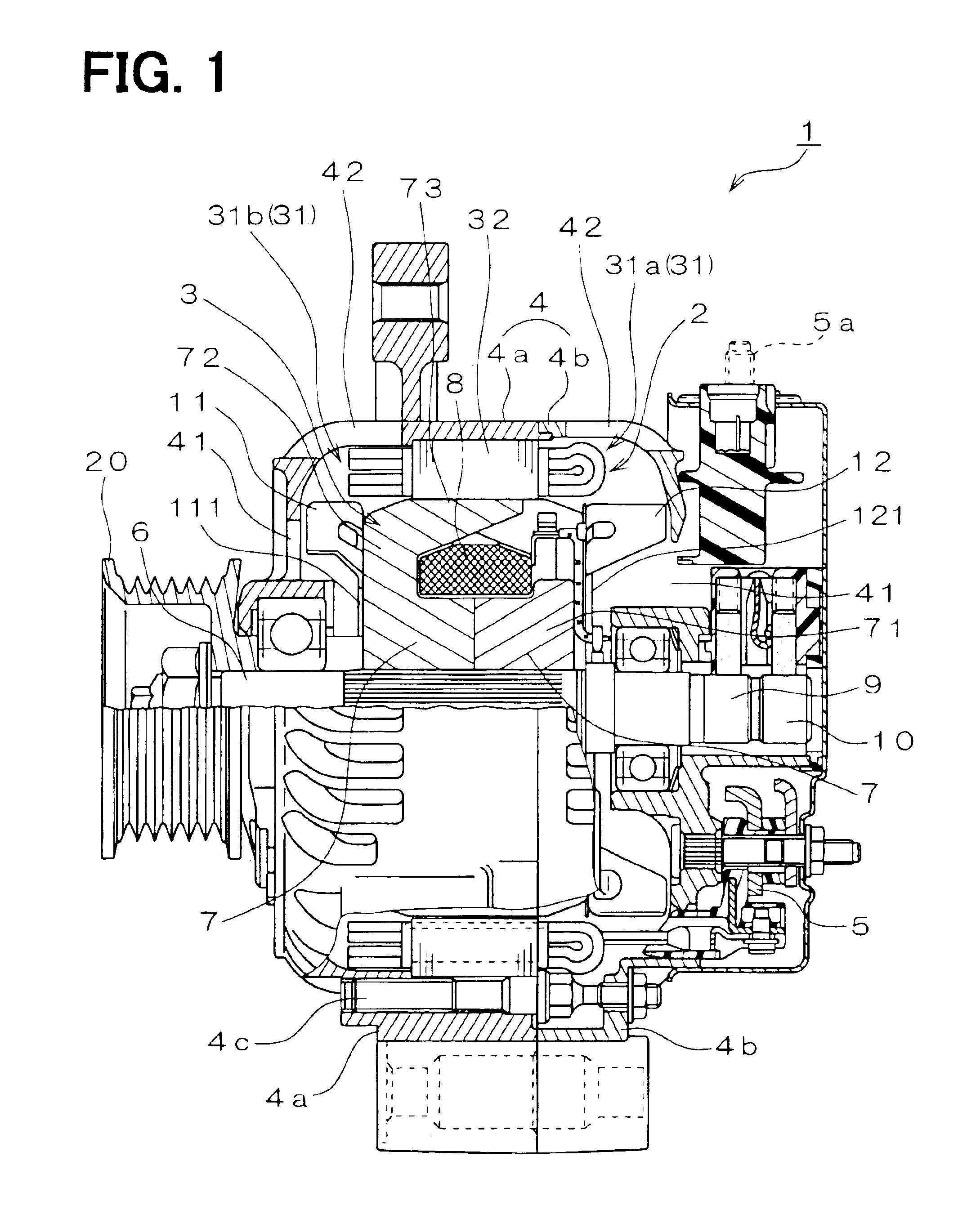
[0031]As shown in FIG. 1, a vehicle ac generator 1 according to the preferred embodiment of the invention includes a stator 2, a rotor 3, a housing 4, a rectifier unit 5 and others.

[0032]The rotor 3 functions as a magnetic field generator and rotates together with a shaft 6. The rotor 3 includes a pole core unit 7, a field coil 8, a pair of slip rings 9, 10, a mixed flow fan 11 and a centrifugal fan 12. The shaft 6 carries a pulley 20 that is rotated by an engine via a belt. The pole core unit 7 has twelve claw-shaped magnetic poles 73 and is composed of a pair of pole core members. Each pole core member has a boss portion 71, a disk portion 72 and six claw-shaped magnetic poles 73.

[0033]The mixed flow fan 11 is fixed by welding to the end of the rotor 3 near the pulley 20. The mixed flow fan...


PUM

PropertyMeasurementUnit
Angleaaaaaaaaaa

Abstract

A rotary electric machine stator includes a stator core having plural slots and a stator winding that is composed of plural conductor segments. Each conductor segment has a straight portion disposed in the slot and connection ends projecting from the slots and welded to another. The connection ends to be welded cross each other at an angle larger than zero degree.

Description

CROSS REFERENCE TO RELATED APPLICATION[0001]The present application is based on and claims priority from Japanese Patent Application 2002-53114, filed Feb. 28, 2002, the contents of which are incorporated herein by reference.BACKGROUND OF THE INVENTION[0002]1. Field of the Invention[0003]The present invention relates to a stator of a rotary electric machine to be mounted in a vehicle such as a passenger car or a truck and a method of manufacturing such a stator.[0004]2. Description of the Related Art[0005]As the output power of the vehicle generators has been increasing in order to operate various vehicle safety devices. It is well known that the output power of a vehicle ac generator can be increased if the space factor of a stator winding to stator core's slots is increased, which reduces the resistance of the stator winding. The space factor can be increased if the conductors or wires of the stator winding inserted in the slots are snugly fitted to the slots.[0006]For example, Ja...

Claims


Application Information

Patent Timeline
IPC IPC(8): H02K3/50H02K15/00H02K15/08H02K15/085H02K3/04H02K15/04
CPCH02K3/505H02K15/0056H02K15/0081Y10T29/49009Y10T29/49071Y10T29/53143
Inventor KATO, MITSURU
Owner DENSO CORP
Why Eureka
Try Eureka