Embedded fiber optic demodulator

a fiber optic demodulator and embedded technology, applied in the direction of optical apparatus testing, instruments, transportation and packaging, etc., can solve the problems of egress of cables from composite members, complicated tooling, fragile external portion of optical fibers, etc., to enhance the shm capabilities of platforms

Inactive Publication Date: 2005-08-16
THE BOEING CO
View PDF7 Cites 45 Cited by
  • Summary
  • Abstract
  • Description
  • Claims
  • Application Information

AI Technical Summary

Benefits of technology

[0005]In a preferred embodiment, the present invention provides a composite material that includes laminated layers, an optical fiber, and a demodulator. The layers define a surface portion generally parallel to the layers and an edge portion generally perpendicular to the layers. The optical fiber and demodulator are embedded in the material. The demodulator is optically coupled to the optical fiber and demodulates light transmitted through the fiber. Thus, the composite materials provided by the present invention may be employed on mobile platforms (e.g. aircraft) to enhance the SHM capabilities of the platforms. In particular, embedding the demodulator in the composite material, along with the optical fiber, enables reliable “on demand” interrogation of the SHM sensors which are integral with the optical fiber embedded in the composite material.

Problems solved by technology

Because the transmitters and demodulators discussed above are external to the composite members, the optical fiber must extend from the member, thereby presenting several problems.
For instance, the external portion of the optical fibers are fragile and exposed to mechanical abuse.
Also, the egress of the cables from the composite members complicates the tooling (particularly the bonding jig) required for fabrication of the members.

Method used


Image

  • Embedded fiber optic demodulator
  • Embedded fiber optic demodulator
  • Embedded fiber optic demodulator

Examples


Embodiment Construction

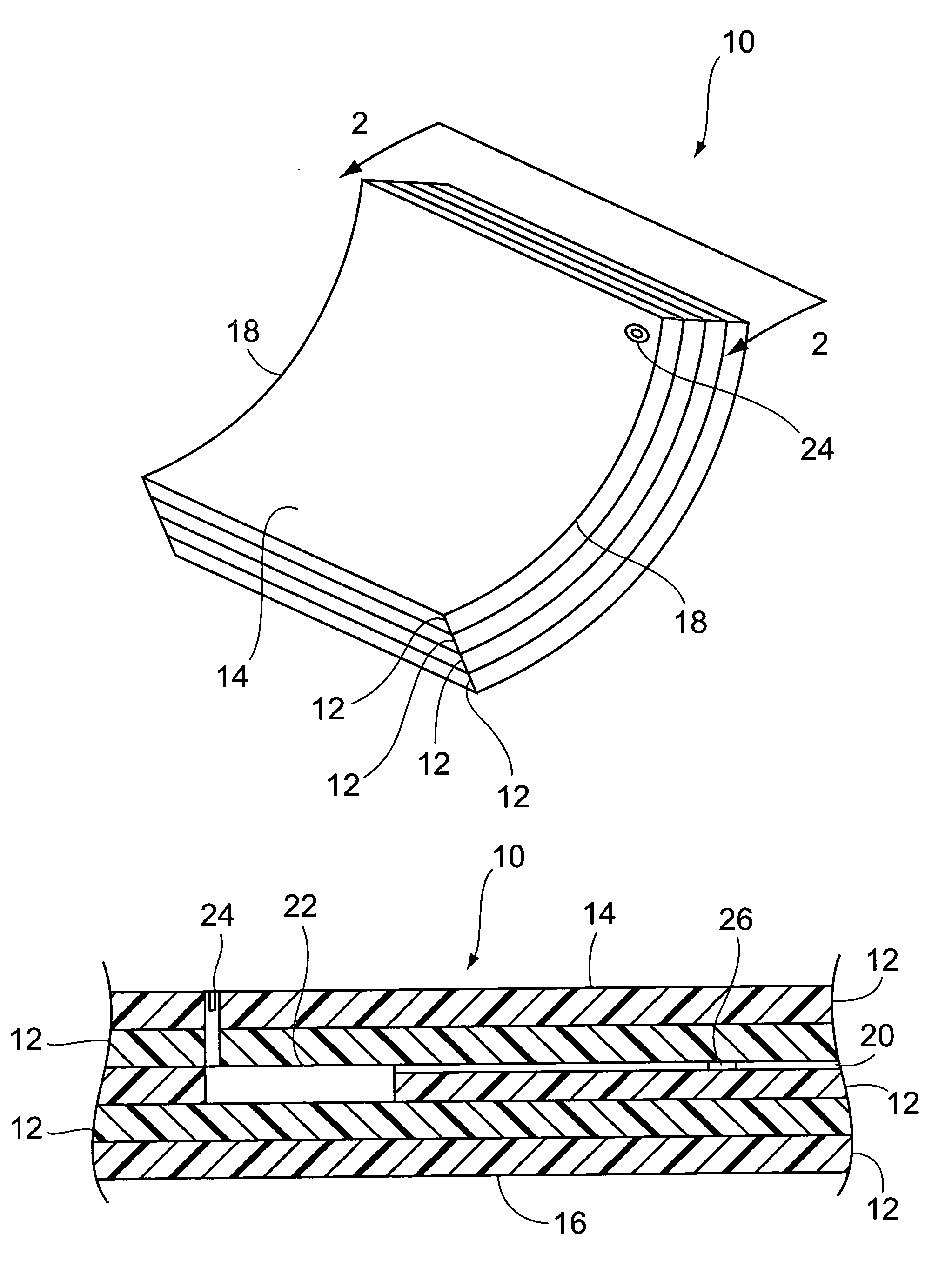
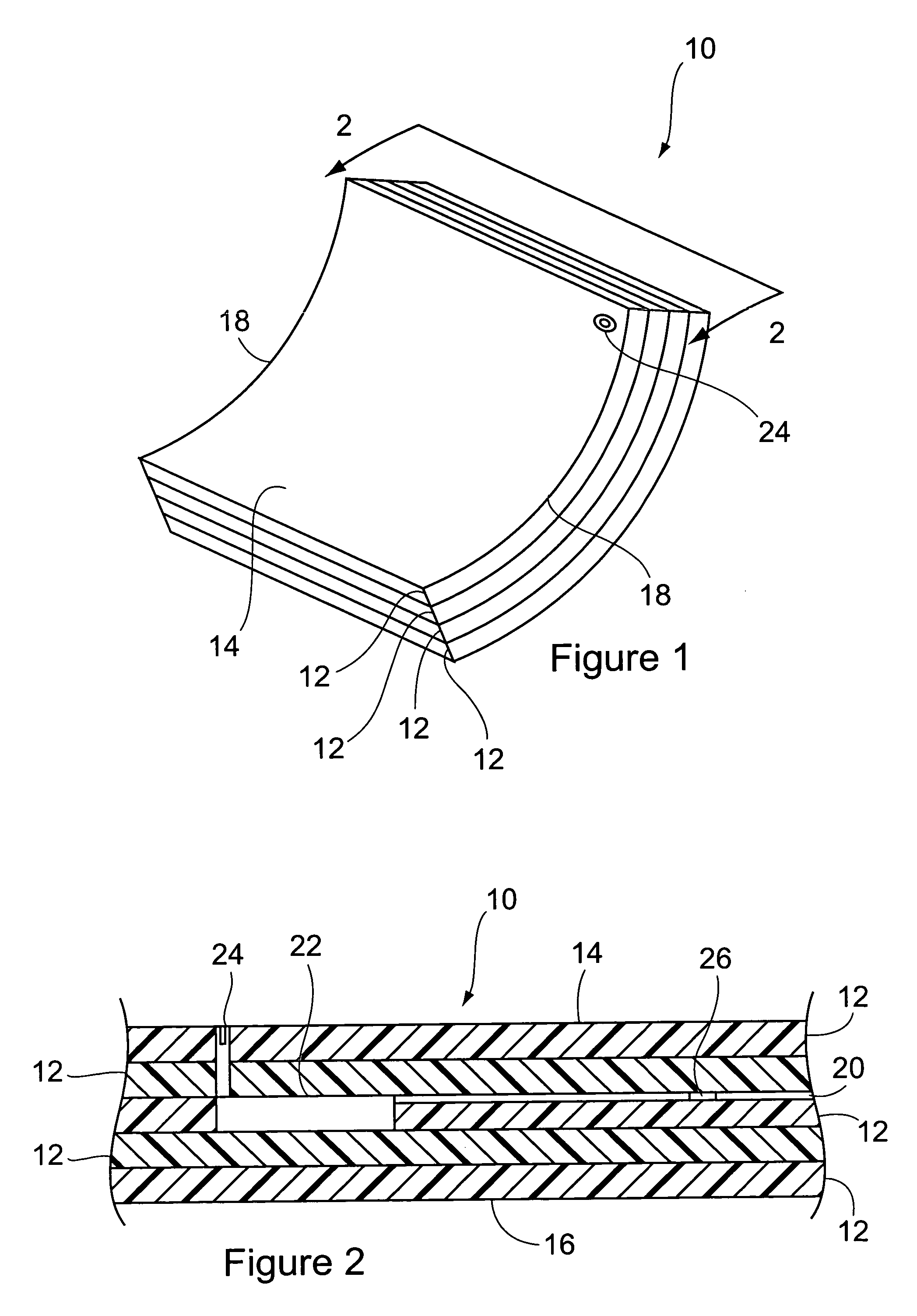
[0015]Referring to the accompanying drawings in which like reference numbers indicate like elements, FIG. 1 illustrates a composite structural member constructed in accordance with the present invention. The composite member 10 shown is generally planar, although curvilinear and spiral-wound members 10 are within the scope of the present invention. Likewise, injection molded, roto molded materials, and similar non-metallic materials are within the scope of the present invention. As shown, the member 10 is generally composed of layers 12 of material (e.g. carbon fiber tows) built upon each other and infused with a matrix binder. Typically, the member 10 includes a tool side (unfinished) surface 14, a finished surface 16 (see FIG. 2), and a plurality of edges 18. The layers 12 are usually trimmed along the edges 18 to allow the member 10 to be placed edge-to-edge with other members to form a larger structure (e.g. an aircraft skin). Because of their unique combination of lightweight a...


PUM

PropertyMeasurementUnit
diameteraaaaaaaaaa
diameteraaaaaaaaaa
temperatureaaaaaaaaaa

Abstract

A composite material is provided that includes laminated layers, an optical fiber, and a demodulator. The layers define a surface portion generally parallel to the layers and an edge portion generally perpendicular to the layers. The optical fiber and demodulator are embedded in the material. The demodulator is optically coupled to the optical fiber and demodulates light transmitted through the optical fiber. A method of monitoring the health of a structural member, which includes a composite material having an optical fiber, is also provided. The method includes demodulating light from the optical fiber using a demodulator embedded in the composite material. Also, a signal representative of the demodulated light is received and interpreted as a condition of the composite material.

Description

FIELD OF THE INVENTION[0001]This invention relates generally to fiber optic demodulators and, more particularly, to fiber optic demodulators used in structural health monitoring applications.BACKGROUND OF THE INVENTION[0002]Optical fibers embedded in composite structural members hold promise for use as structural health monitoring sensors. Current technology employs a combination of an external light source, and an external demodulator, and a protective cable extension that is optically coupled to an optical fiber where the fiber exits the composite member. The external transmitters transmit electromagnetic radiation (hereinafter “light”) into the cables wherein the light encounters optical fiber sensors that cause sensible alterations to the transmitted light. The alterations may be linear (i.e. characterized by the same frequency of the transmitted light) or non-linear and are generally proportional, in some manner, to the condition the sensors are intended to measure. Thereafter,...

Claims


Application Information

Patent Timeline
Patent Type & Authority Patents(United States)
IPC IPC(8): G02B6/42G01D5/353G01M5/00
CPCG01M5/0041G01M5/0091G01D5/3537G01M11/086G02B6/42Y10T428/31504Y10T428/249924
Inventor SHOOKS, JR., WESLEY RAYMONDDUNNE, JAMES P.
Owner THE BOEING CO
Why Eureka
Try Eureka