Line generating device

a generation device and line technology, applied in the direction of lighting support devices, washstands, instruments, etc., can solve the problem of most expensive laser levels

Active Publication Date: 2005-08-23
BLACK & DECKER INC
View PDF7 Cites 19 Cited by
  • Summary
  • Abstract
  • Description
  • Claims
  • Application Information

AI Technical Summary

Benefits of technology

[0004]In accordance with the present invention, an improved line generating device is employed. The line generating device may include a housing, a support assembly mounted within the housing, a light source mounted on the support assembly, a lens mounted on at leas

Problems solved by technology

Most of these laser levels are expensive due t

Method used


Image

  • Line generating device
  • Line generating device
  • Line generating device

Examples


Embodiment Construction

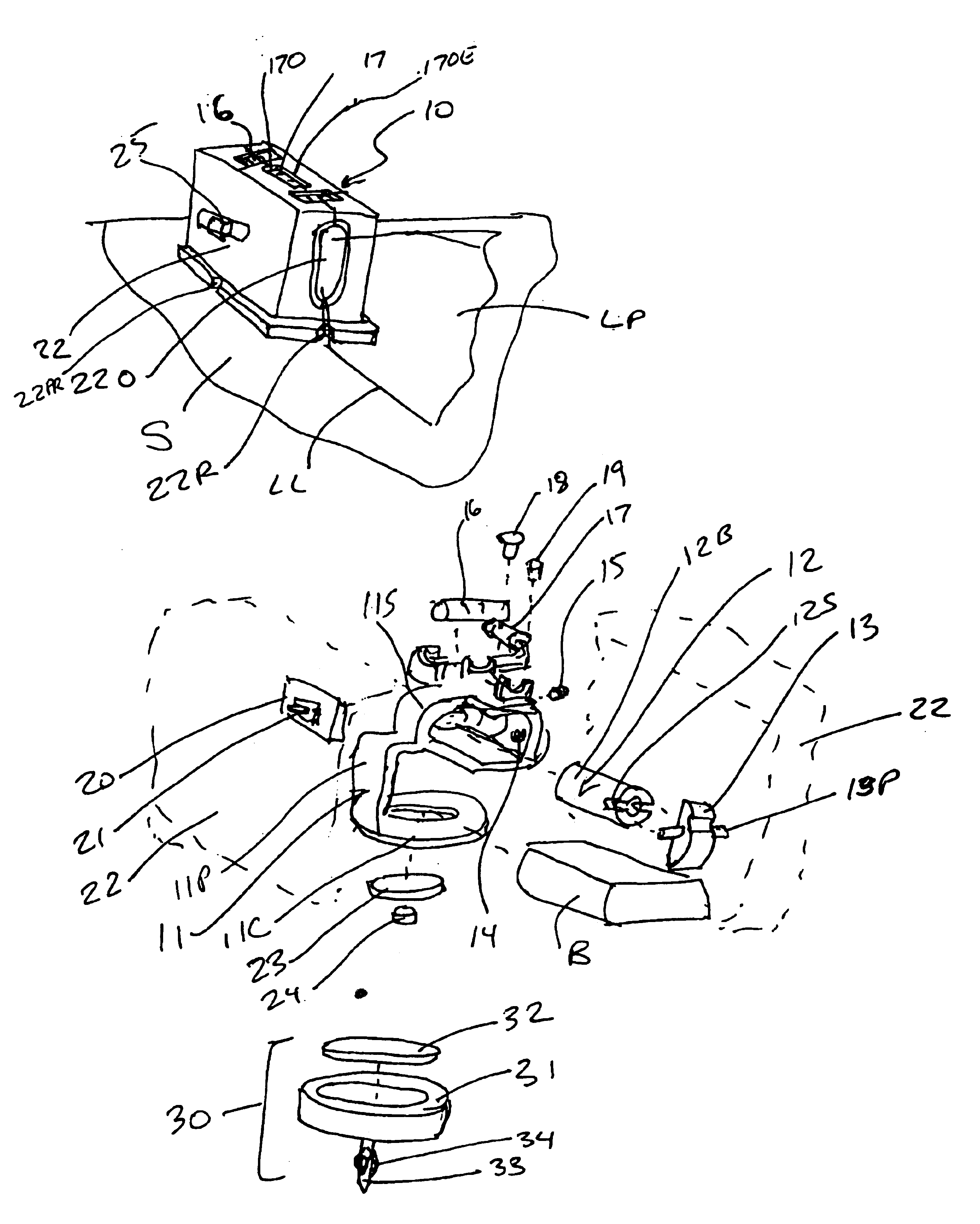
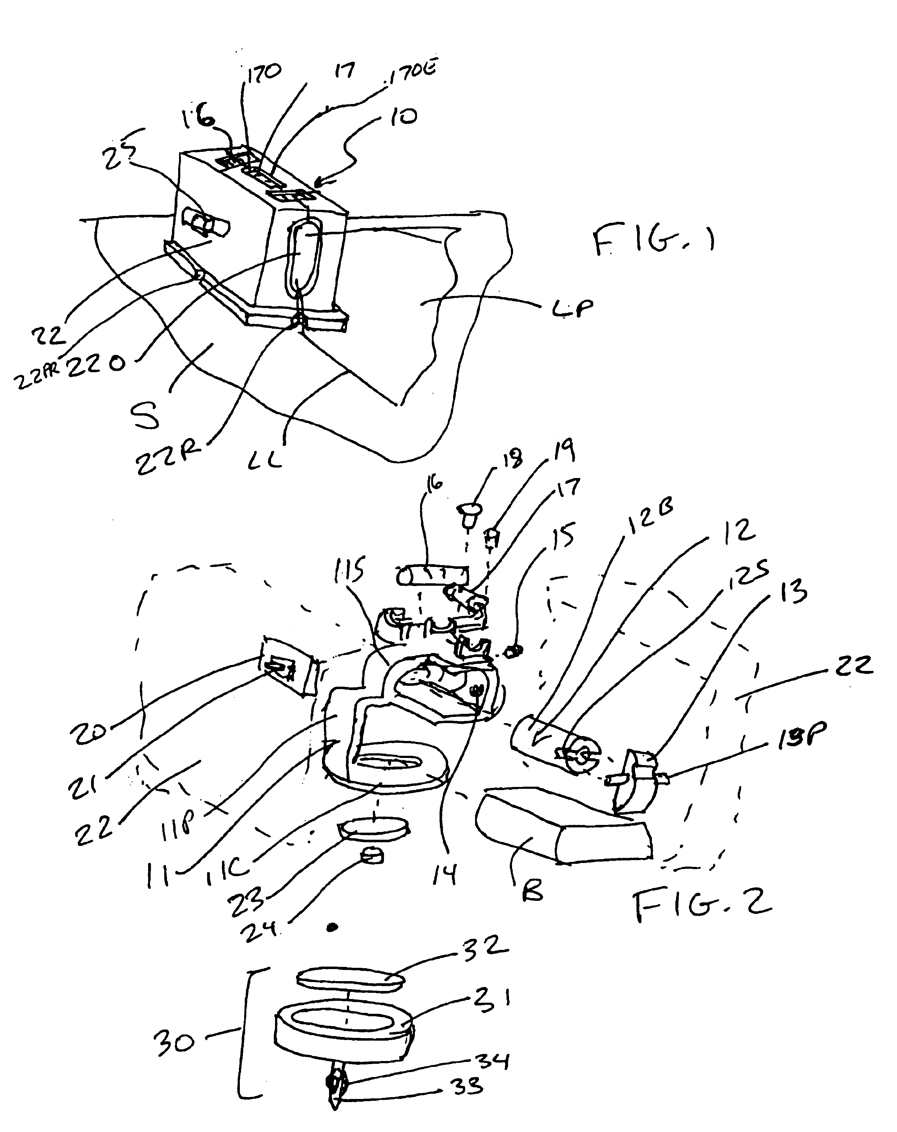
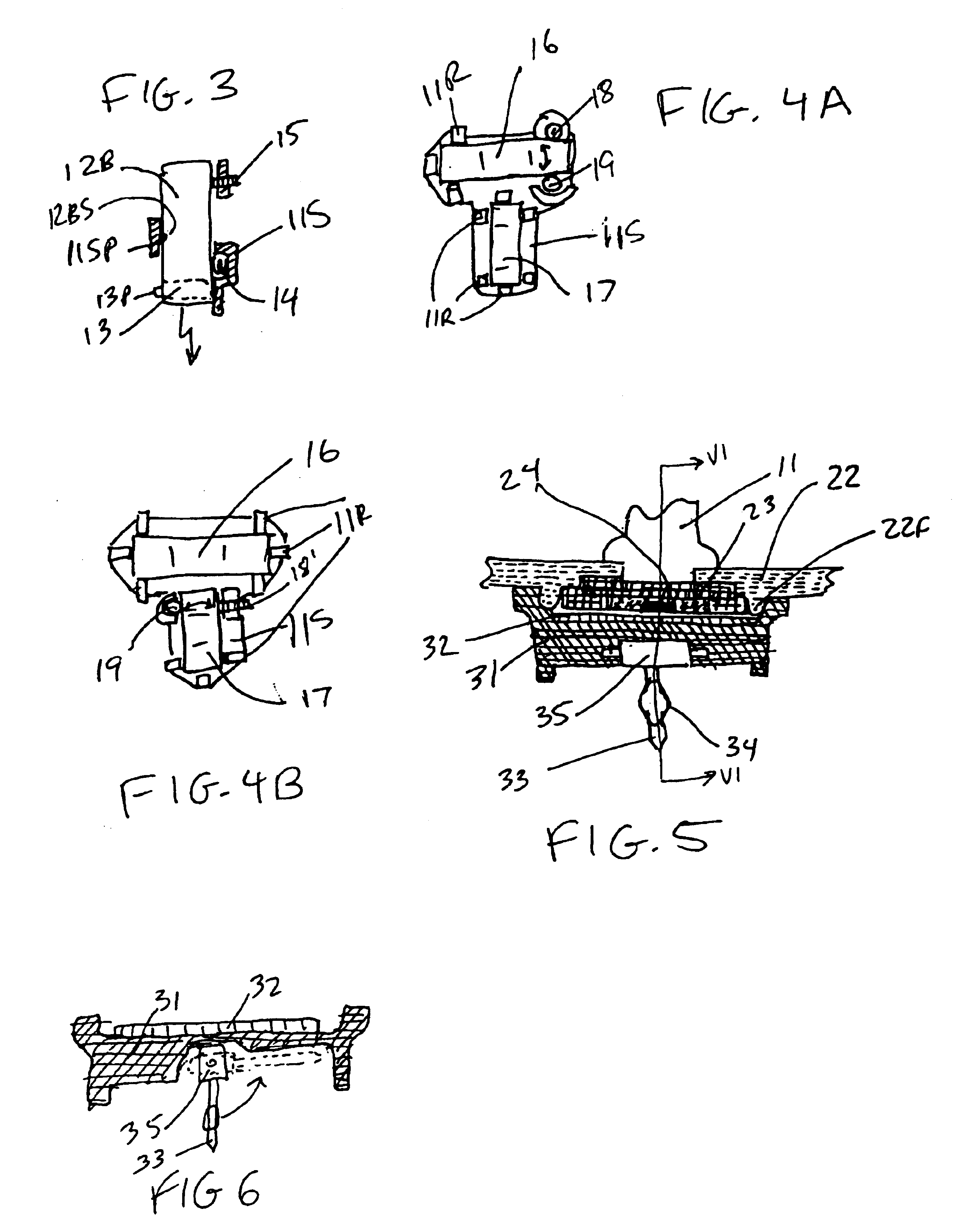
[0015]With reference to FIGS. 1 and 2, a line-generating device constructed in accordance with the teachings of the present invention is generally indicated by reference numeral 10. Line generating device 10 may comprise a frame assembly 11, a diode assembly 12, a lens 13 mounted onto the diode barrel 12, level vials 16, 17 mounted on frame assembly 11, printed circuit board 20, with a switch 21 mounted thereon, battery B received on the frame assembly 11, a switch actuator 25 for actuating switch 21, and a housing 22 for receiving for enclosing most, if not all, of the elements described above.

[0016]Frame assembly 11 is preferably made of metal, such as magnesium or zinc. Frame assembly 11 preferably has a substantially horizontal planar support 11C, a substantially vertical post 11P connected to planar support 11C, and support section 11S for receiving and / or supporting several components. Preferably, support portion 11S receives and supports diode assembly 12 and / or level vials 1...


PUM


Abstract

A line generating device may include a housing, a support assembly mounted within the housing, a light source mounted on the support assembly, a lens mounted on at least one of the support assembly and the light source, the lens receiving light and projecting the light in the shape of a fan within a plane, and a first level vial mounted on the support assembly, wherein the first level vial is coplanar or perpendicular to the plane. The device may also include a magnet mounted on the support assembly.

Description

CROSS-REFERENCE TO RELATED APPLICATIONS[0001]The present application derives priority from U.S. application Ser. No. 60 / 469,160, filed on May 9, 2003, now pending, and U.S. application Ser. No. 60 / 466,685, filed on Apr. 30, 2003, now pending.FIELD OF THE INVENTION[0002]The present invention generally relates to line generating devices and more specifically to laser line generating devices.BACKGROUND OF THE INVENTION[0003]In the construction industry, it is well known to use laser levels for marking reference lines to be used in the layout of different features in a room or structure. Most of these laser levels are expensive due to the optics and electronics involved therein. Accordingly, it is an object of the invention to provide a line generating device that is less expensive to manufacture than the prior art laser levels.SUMMARY OF THE INVENTION[0004]In accordance with the present invention, an improved line generating device is employed. The line generating device may include a ...

Claims


Application Information

Patent Timeline
IPC IPC(8): G01C15/00G01B11/26G01C15/02
CPCG01C15/004G01C15/008
Inventor MARSHALL, JAMES D.SERGYEYENKO, OLEKSIY P.HEAVEL, RICHARD J.TURNER, TERRY L.
Owner BLACK & DECKER INC
Why Eureka
Try Eureka