Console box

a console box and box body technology, applied in the field of console boxes, can solve the problems of degrading the quality of the console box, affecting the appearance, and affecting the appearance of the console box

Inactive Publication Date: 2005-08-23
TOYODA GOSEI CO LTD
View PDF21 Cites 67 Cited by
  • Summary
  • Abstract
  • Description
  • Claims
  • Application Information

AI Technical Summary

Benefits of technology

[0008]Accordingly, it is an objective of the present invention to provide a console box with an armrest that is moved smoothly.

Problems solved by technology

At this time, the armrest can rattle due to insufficient rigidity, which degrades quality of the console box.
Further, when the armrest is at the lifted position, the four bar linkage is exposed, which degrades the appearance and may cause foreign matter to be caught between the linkage and the armrest.
Therefore, the armrest is likely to rattle in the lateral direction when being slid.
However, the structure is complicated and increases the cost.
This degrades the usability.
This structure not only limits the shapes of the storage chamber and the lid, but also limits the entire shape of the console box.
The lid therefore cannot function as an armrest.

Method used


Image

  • Console box
  • Console box
  • Console box

Examples


first embodiment

[0046]the present invention will now be described with reference to FIGS. 1 to 6.

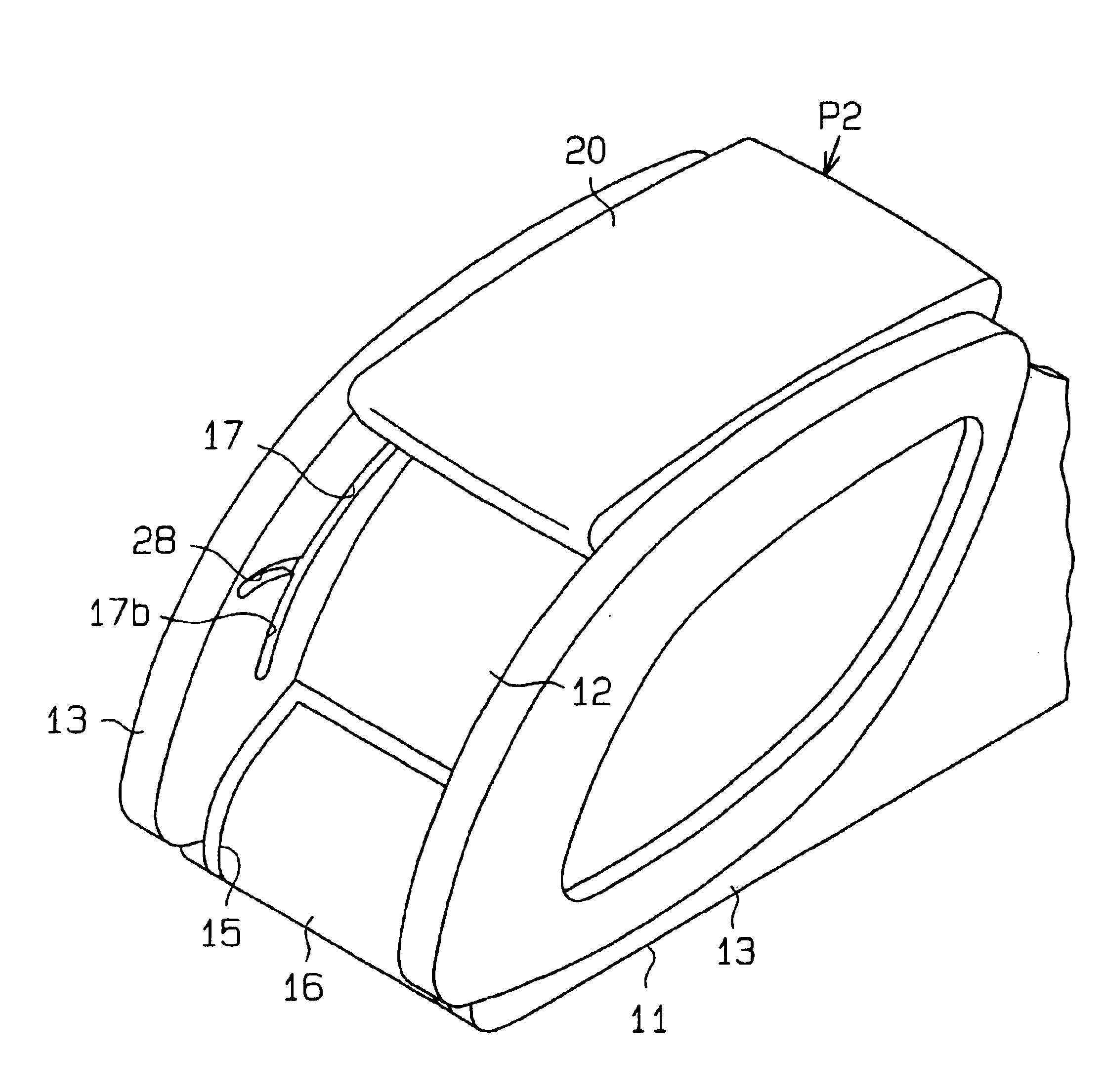
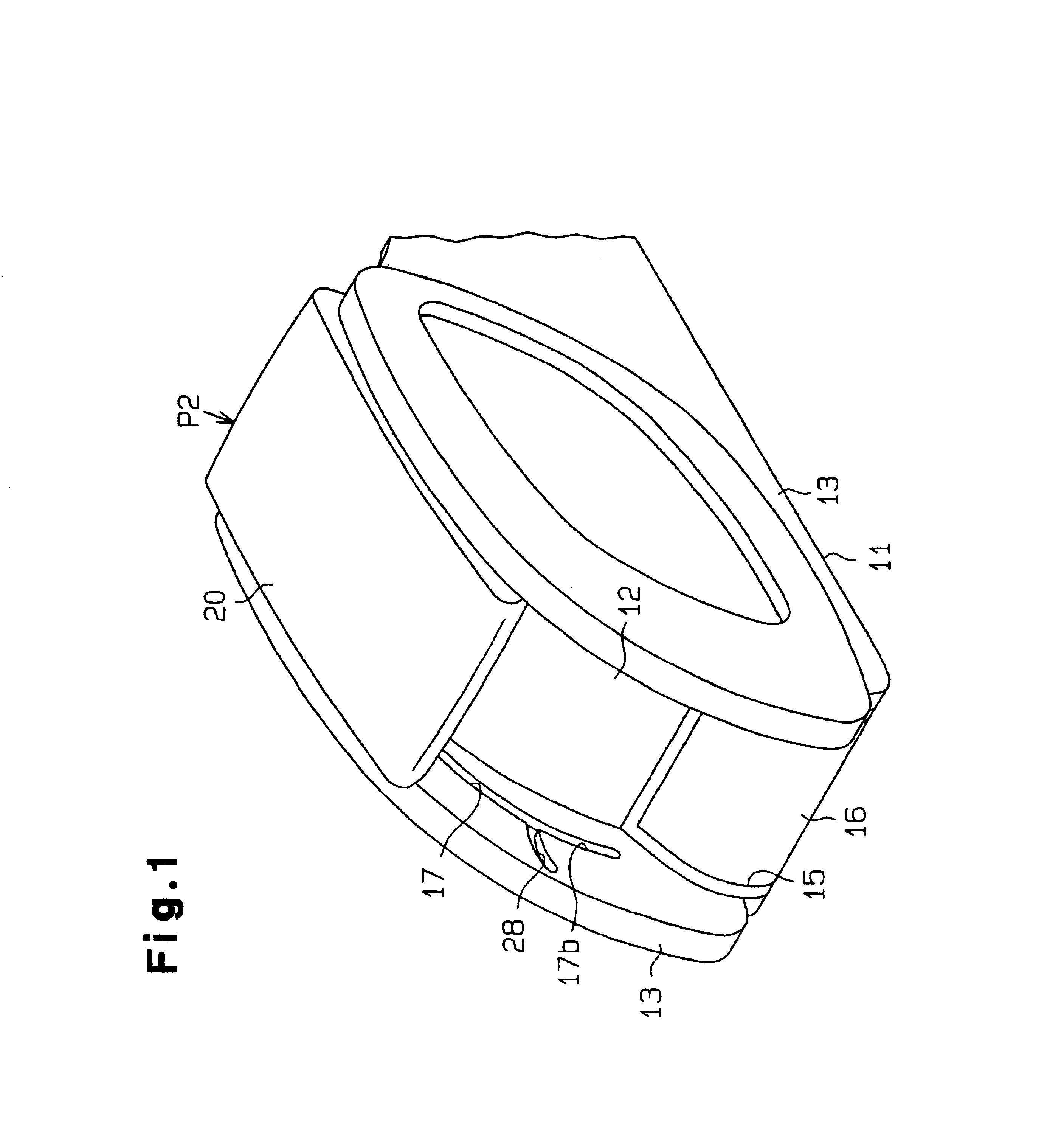
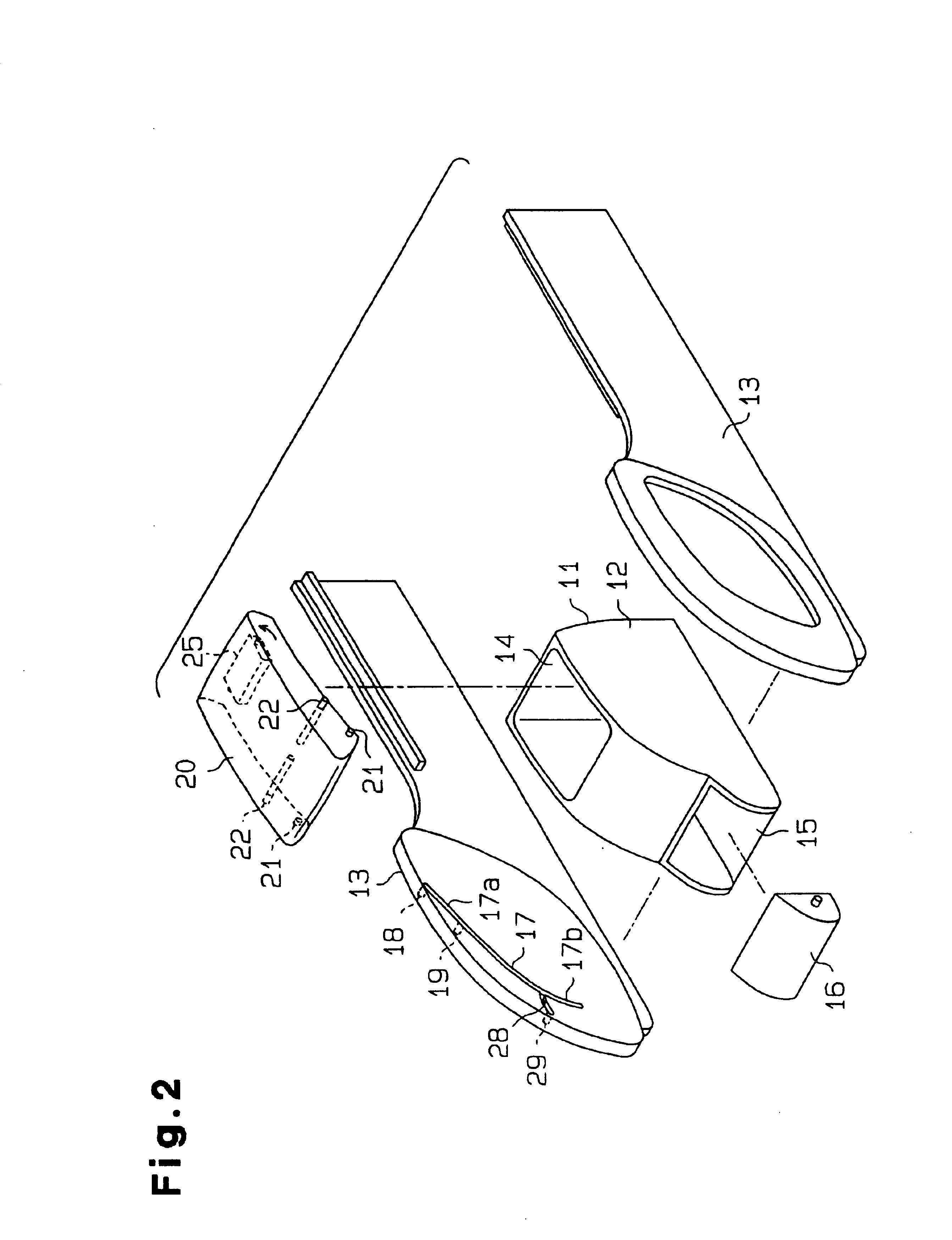
[0047]A console box 11 illustrated in FIGS. 1 to 3 is located between the driver's seat and the front passenger seat of a vehicle. The console box 11 includes a box main body 12, which is made of a synthetic resin. Left and right sidewalls 13 made of a synthetic resin are attached to the left side and the right side of the box main body 12 with fasteners such as pins (not shown). A storage chamber 14 having an upper opening is formed in a center portion of the box main body 12. A pocket 15 is formed in a rear portion of the box main body 12. A resin ashtray 16 or a case for small articles is rotatably attached to the pocket 15.

[0048]As shown in FIGS. 1 to 4, a guide groove 17 is formed in the inner surface of each sidewall 13. The guide grooves 17 function as guide portions. Each guide groove 17 has a front inclined section 17a and a substantially arcuate rear inclined section 17b. The front inclined se...

fourth embodiment

[0097]As shown in FIGS. 19 and 20, a pair of left and right guide members 59 are formed on the upper surface of the lower wall of the armrest 20, and a pair of left and right guide members 60 are formed on the lower surface of the upper wall of the armrest 20. A flat guide surface 59a is formed on the inner surface of each guide member 59. The flat guide surfaces 59a extend along the moving direction of the vehicle. A convex shaped arcuate guide surface 59b is formed at the rear end of each guide member 59. A concave shaped arcuate guide surface 60a is formed in the front end of each guide member 60. The arcuate guide surface 60a of each guide member 60 corresponds to the arcuate guide surface 59b of the corresponding guide member 59. A moving member, which is a movable plate 50, is movably supported between the flat guide surfaces 59a of the guide members 59. As in the fourth embodiment, the front end of the movable plate 50 is coupled to the lever 25 with coupler pins 52.

[0098]A c...

seventh embodiment

[0108]In the seventh embodiment, a pocket 70 is formed in a rear part of the box main body 12. A cover 71 is provided at the pocket 70. The cover 71 covers rear section of the guide grooves 17 from above and functions as a lid of the pocket 70.

[0109]That is, as shown in FIGS. 24 to 26, the cover 71 is supported by the sidewalls 13 with support shafts 72 provided at the front end. The support shafts 72 are engaged with small holes formed in the sidewalls 13 so that the cover 71 pivots vertically. The cover 71 is biased upward by torsion springs 73. When the armrest 20 is at the front closing position P1 to close the upper opening of the storage chamber 14, the cover 71 is biased by the force of the coil springs 73 and located at an upper position. In this state, a hook portion 74 is engaged with an engaging end 75 formed in the rear wall of the pocket 70. The cover 71 is therefore closes the pocket 70. FIG. 23 illustrates a state in which the armrest 20 is at the front closing positi...


PUM


Abstract

A console box of the present invention has a box main body, a pair of sidewalls, and an armrest. The box main body is located between the sidewalls, and the armrest is located above the box main body. Each sidewall has a guide groove extending in the moving direction of the vehicle. The armrest has a pair of engaging pins. Each engaging pin is engaged with and slides along one of the guide grooves. Thus, the armrest smoothly slides along the moving direction of the vehicle.

Description

BACKGROUND OF THE INVENTION[0001]The present invention relates to a console box located between the driver's seat and a front passenger seat in a vehicle such as an automobile.[0002]The following patent and utility model publications disclose typical console boxes. Japanese Laid-Open Utility Model Publication No. 5-95349 discloses as console box with an armrest that also functions as a lid. The armrest is attached to a box main body with a four-bar linkage to cover the upper opening. Japanese Laid-Open Patent Publication No. 2000-103289 and No. 2000-159026 disclose console boxes each having an armrest that also functions as a lid. The armrest is slidably attached to a box main body with a pair of guide rails to cover the upper opening.[0003]Japanese Laid-Open Utility Model Publication No. 4-133951 discloses a console box with a curved top surface. Specifically, the top surface has an arcuate cross-section along a plane perpendicular to the moving direction of the vehicle. An opening...

Claims


Application Information

Patent Timeline
Patent Type & Authority Patents(United States)
IPC IPC(8): B60N2/46B60N2/75B60N3/00B60R7/04
CPCB60N2/4646B60N2/4686B60R7/04B60N2/773B60N2/793
Inventor NIWA, KENJIYAMAUCHI, AKIRAYABUYA, SHIGERUOZAWA, ETSUOSATO, TAKAHIKOIMAMURA, HIROKISHIMIZU, YUJI
Owner TOYODA GOSEI CO LTD
Why Eureka
Try Eureka