Preloadable retainer

a retainer and pin technology, applied in the direction of screws, threaded fasteners, snap fasteners, etc., can solve the problems of large amount of force, difficult installation, and difficulty in inserting parallel legs into small apertures, and achieve the effect of simple insertion of pins into apertures in items to be fastened, no force, and extra flexibility

Inactive Publication Date: 2005-08-23
NAT MOLDING
View PDF15 Cites 28 Cited by
  • Summary
  • Abstract
  • Description
  • Claims
  • Application Information

AI Technical Summary

Benefits of technology

[0009]It is therefore an object of the invention to provide a fastener that is simple to install with a low amount of force.
[0010]It is another object of the invention to provide a fastener that is strong and reliable.

Problems solved by technology

While this type of fastener is widely used, the closed V-shape of the anchor makes it difficult to install.
These fasteners all suffer the same drawback as Beglinger: the closed V formation of the anchor is so resistant to bending that a large amount of force is required to insert the fastener, and bring it into a locked position.
This fastener suffers the drawback that the parallel legs are more difficult to insert into a small aperture in the item, as they must often be squeezed together by the operator's fingers in order for the anchor to be inserted.

Method used


Image

  • Preloadable retainer
  • Preloadable retainer
  • Preloadable retainer

Examples


Embodiment Construction

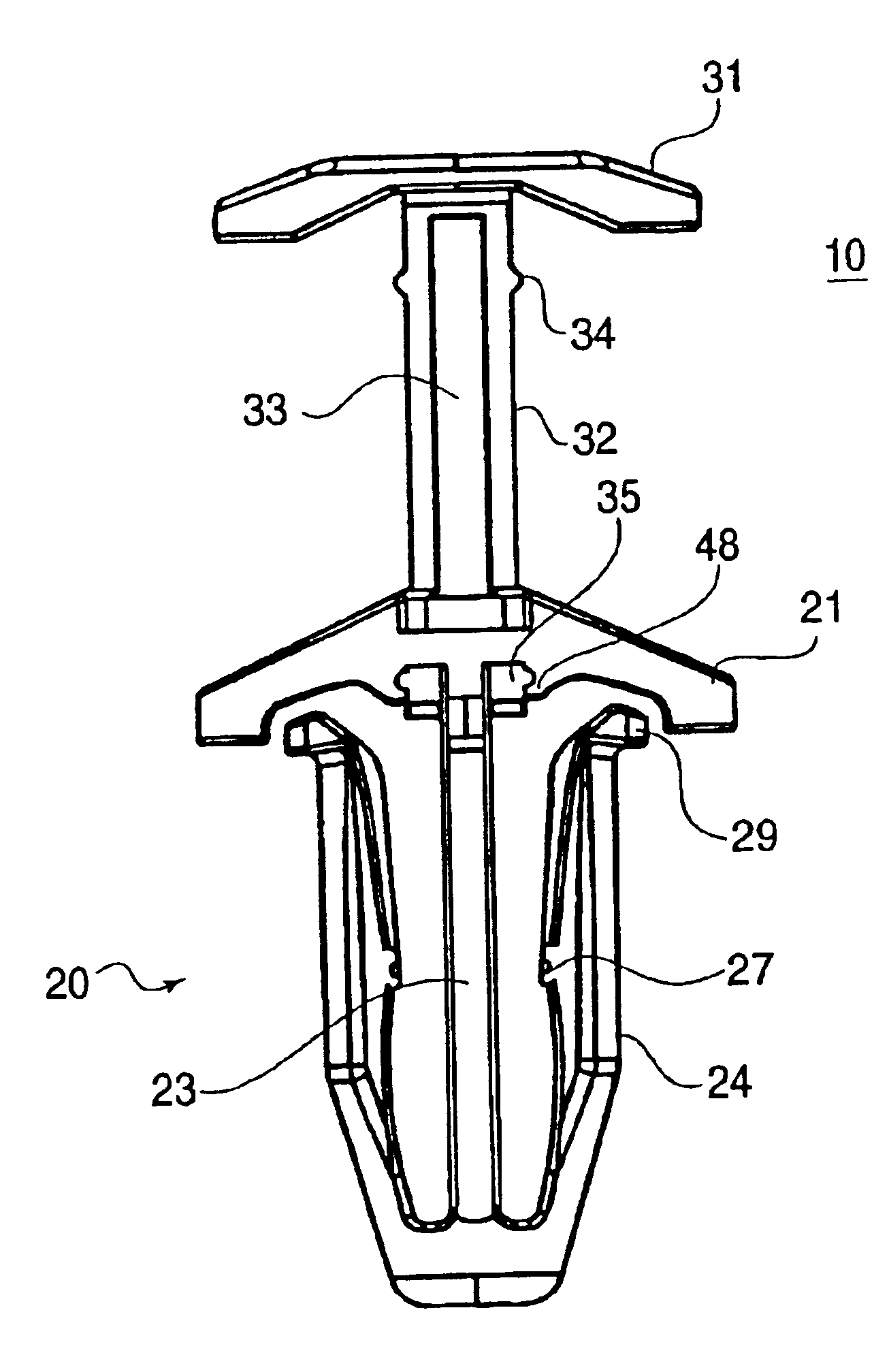
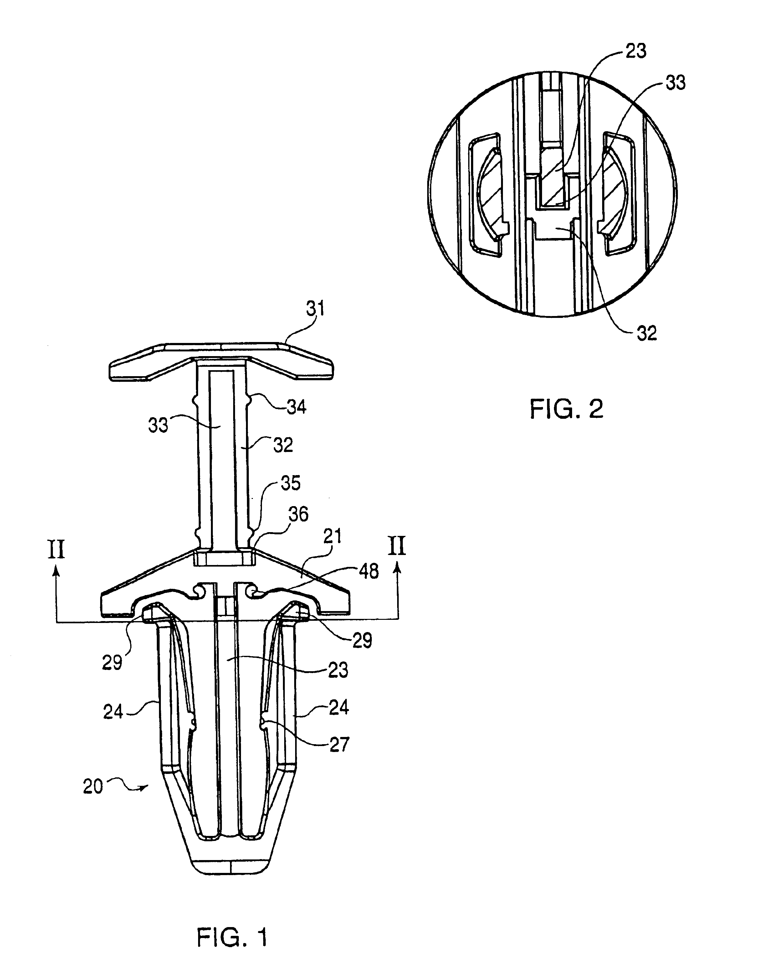
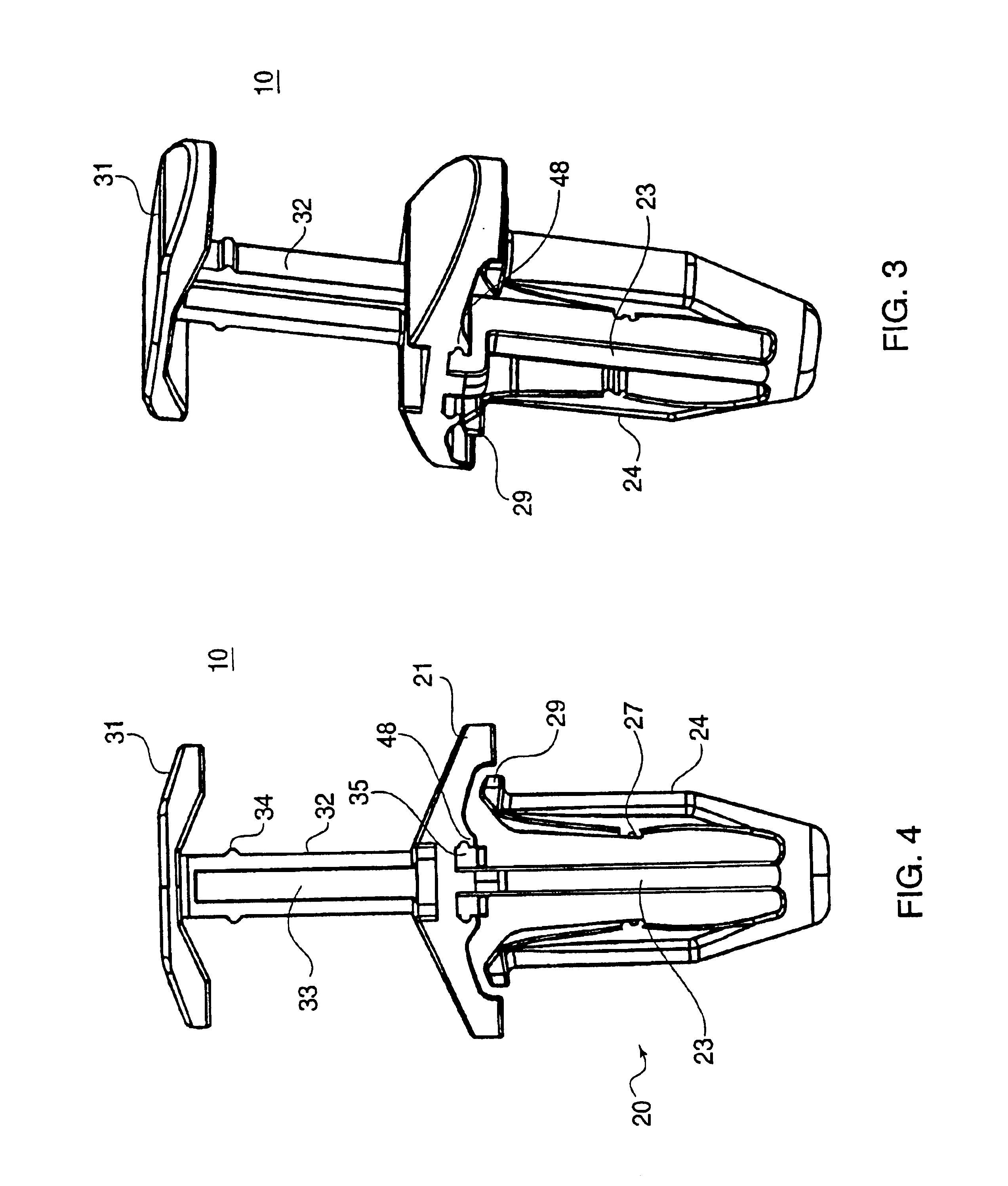
[0029]Referring now in detail to the drawings, FIGS. 1-7 show the fastener 10 according to the invention as it goes from an initially molded state (FIG. 1) into a fully locked position (FIG. 7). FIG. 1 shows the fastener 10 according to the invention in an initial molded state. Fastener 10 comprises an anchor 20 and a push pin assembly 30. Anchor 20 has a top plate 21 connected to a central leg 23. Central leg 23 extends substantially perpendicular to the bottom surface of top plate 21. There are two flexible anchor arms 24 connected to the free end of central leg 23. Each anchor arm 24 extends up and away from central leg 23. At the free end of each anchor arm 24 is a lip 29.

[0030]Push pin assembly 30 comprises a push button 31 and a pin 32 connected to and extending downward from the bottom surface of push button 31. Pin 32 is adapted to fit through an aperture 22 in top plate 21, such that pushing push button 31 causes pin 32 to extend through the aperture 22 as push button 31 is...


PUM


Abstract

A fastener comprises an anchor and a central pin. The anchor has a top plate to which a central leg is connected. At the free end of the central leg are two anchor arms that extend up and outward from the free end, forming an arrowhead shape. Each anchor arm has an outwardly extending lip connected to its free end. The anchor arms are flexible and can flex inward as the anchor is placed through a hole in an item to be fastened. Connected to the top surface of the top plate is a push pin. Depressing the push pin breaks the connection areas to create a two-piece anchor from the single part. The push pin comprises a push button and a pin connected to the underside of the push button. The pin consists of a vertical post having a channel therein for accommodating the central leg of the anchor. Pushing the push button downward causes the anchor arms to be pushed outward and to anchor the fastener into the items to be fastened.

Description

CROSS REFERENCE TO RELATED APPLICATIONS[0001]This is a continuation-in-part of U.S. patent application Ser. No. 10 / 456,665 filed on Jun. 6, 2003, the disclosure of which is herein incorporated by reference.BACKGROUND OF THE INVENTION[0002]1. Field of the Invention[0003]This invention relates to a preloadable retainer for fastening two planar objects together. In particular, the invention relates to a fastener comprising an anchor and a push pin that is particularly useful for fastening automotive body panels to sheet metal.[0004]2. The Prior Art[0005]Anchor type fasteners having a central pin are known. For example, U.S. Pat. No. 4,571,134 to Beglinger et al. shows a two-piece plastic fastener comprising an anchor and a central pin. The anchor comprises a closed V-shaped insertion portion and a top plate. The anchor is placed through two (or more) planar items to be fastened together. A central pin extends down between the arms of the V and causes the arms to spread when the pin is ...

Claims


Application Information

Patent Timeline
Patent Type & Authority Patents(United States)
IPC IPC(8): F16B19/04F16B19/10
CPCF16B19/1081Y10T24/309
Inventor ANSCHER, JOSEPHMATWEY, PAUL
Owner NAT MOLDING
Why Eureka
Try Eureka