
Ratchet assembly for electric fan

a technology of ratchets and fans, applied in the direction of machines/engines, machine supports, liquid fuel engines, etc., can solve the problems of less than 45 degrees of pivoting and the fan may rotate to an undesirable position

Inactive Publication Date: 2005-08-23
LASKO OPERATION HLDG LLC
View PDF16 Cites 19 Cited by
  • Summary
  • Abstract
  • Description
  • Claims
  • Application Information

AI Technical Summary

Benefits of technology

[0006]In view of the shortcomings of the prior art, the present invention provides a ratcheting mechanism that allows a fan head to be tilted relative to its base, without the need for loosening and tightening of bolts or other securing mechanisms.
[0012]According to still another aspect of the present invention, a first stop is provided at a first position on the pivot and a second stop is provided at a second position on the pivot to limit the tilting range of the fan head.
[0016]According to still a further aspect of the present invention, at least one of the side walls has at least one protrusion extending substantially orthogonal relative to an outer surface of the side wall, and its respective cover has at least one mating portion extending from a surface of an inner side of the cover, the at least one mating portion disposed against the at least one protrusion for preventing rotation of the cover relative to the side wall.

Problems solved by technology

Due to the frictional forces between the yoke and the thumbscrews, these fans may not stay in the position where they are placed and the fan may rotate to an undesirable position due to loosening of the thumbscrews.
This has disadvantages, however, in that the degree of pivoting was limited to less that 45 degrees due to the torsional pressure exerted by the counter balance spring, in addition to the extra steps required by the user in the loosening / tightening operations.

Method used


Image

  • Ratchet assembly for electric fan
  • Ratchet assembly for electric fan
  • Ratchet assembly for electric fan

Examples


Embodiment Construction

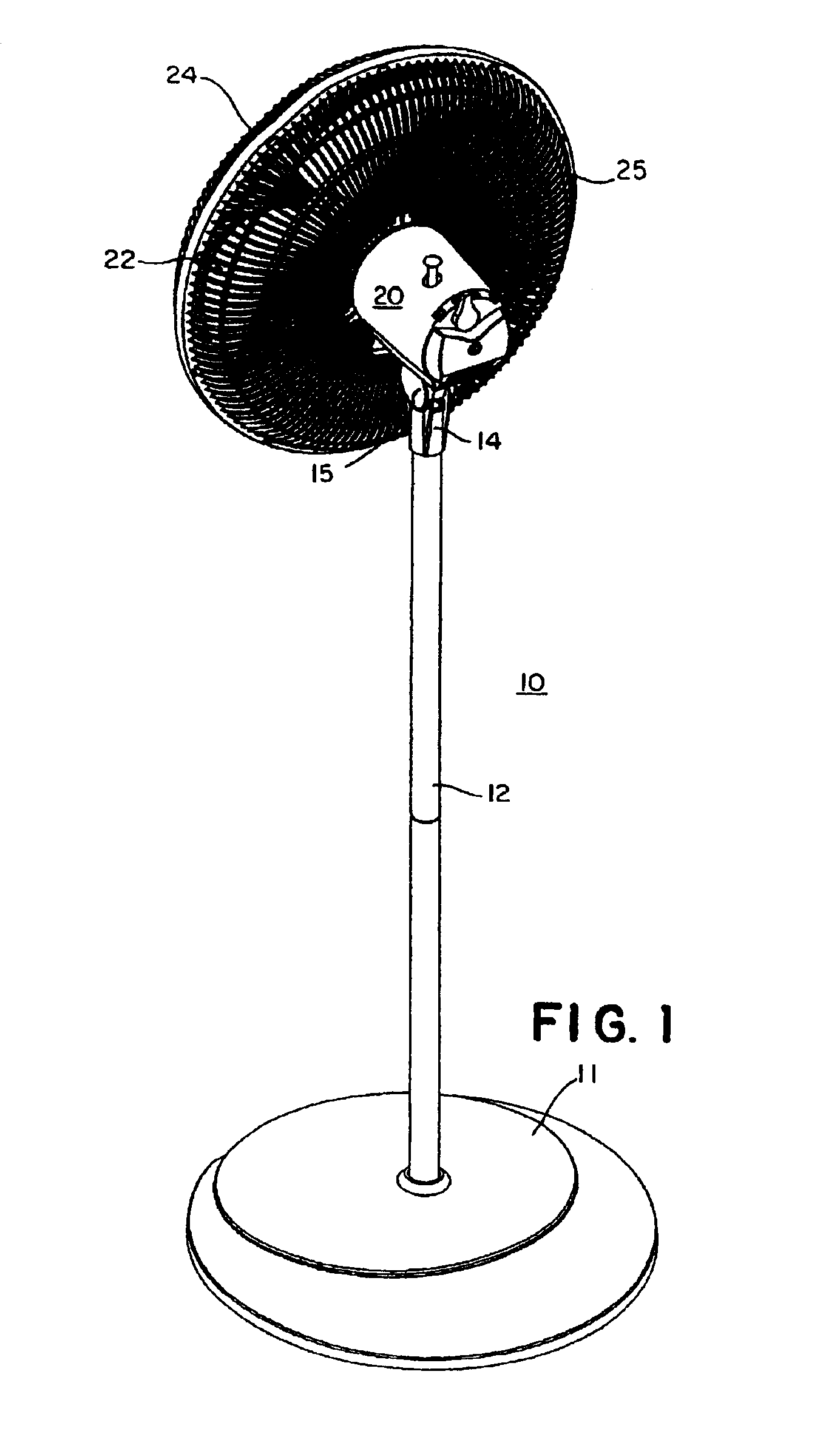
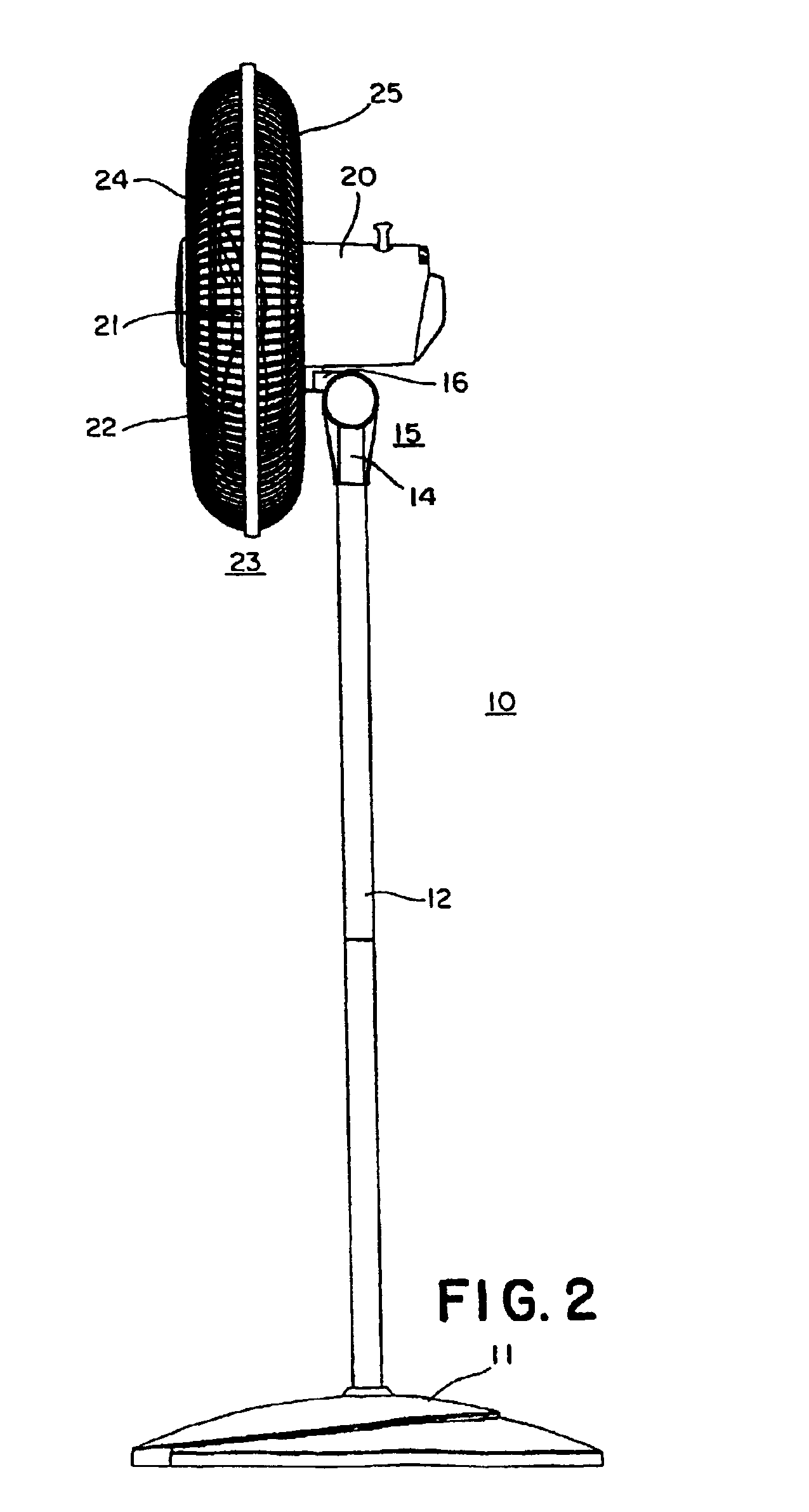
[0034]Referring now more particularly to FIGS. 1-3, a fan 10 is illustrated. Fan 10 includes a base 11 with a length of tubing 12 carried therein. Tubing 12 may be a single piece of a desired length or made of multiple pieces coupled together; the latter being for ease of packaging and shipment. Although a pedestal fan is illustrated in association with an exemplary embodiment of the present invention, the invention is no so limited and may be incorporated in other types of fans, such a table top fans, etc.

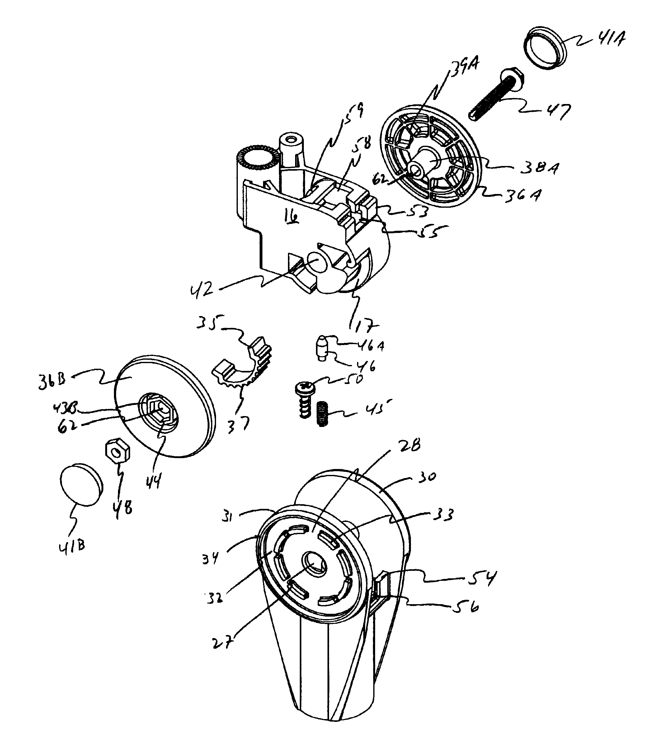
[0035]Tubing 12 is coupled to extension 14 of ratchet assembly 15 (described in detail below). Ratchet assembly 15 has a pivot 16 (to be described), which has a fan motor assembly 20 attached thereto in well known manner, and which can be rotated or oscillated from side to side about ratchet assembly 15.

[0036]Referring now to FIG. 2, fan motor assembly 20 has a fan hub 21 extending therefrom, with a plurality of fan blades 22 which are encased in fan grill 23. In the example shown...


PUM


Abstract

A ratcheting mechanism for a fan having a base and a head assembly. The ratcheting mechanism has a pivot having a portion for coupling with the fan head assembly; a member disposed within a portion of the pivot; a extension portion having side walls spaced apart from one another, the pivot and member disposed between the side walls of the extension portion; a pin having a lower portion seated within a base portion of the extension portion, an upper portion of the pin resiliently placed against the collar; and a coupling placed through a central portion of the side walls and the pivot for compressing the side walls against the pivot to maintain a position of the fan head assembly and allowing bi-directional pivoting of the pivot relative to the extension portion in a range of greater than 45 degrees absent a tightening and a loosening of the coupling.

Description

FIELD OF THE INVENTION[0001]This invention relates to a fan of the type which has a fan motor assembly carried on a single ratchet assembly for selective positioning of the fan. More specifically, the present invention relates to a ratchet assembly for a fan that allows the head of the fan to tilt relative to its base.BACKGROUND OF THE INVENTION[0002]Fans, such as pedestal fans, are well known in the art. Such fans allow positioning of the fan above the floor, and usually have a yoke attached to tubing which is carried in a base; the yoke being attached to the fan by a pair of thumbscrews, which extend through the ends of the yoke into captive nuts in the grills surrounding the fan blades. An example of such fans is shown in my prior U.S. Pat. No. 5,368,445. While these fans are satisfactory, the yoke style of mounting the fan requires that the two thumbscrews be loosened to rotate the fan and then tightened. Due to the frictional forces between the yoke and the thumbscrews, these f...

Claims


Application Information

Patent Timeline
Patent Type & Authority Patents(United States)
IPC IPC(8): F04D29/60F16C11/10F04D29/64F16C11/04F16M11/06F16M11/02
CPCF04D29/601F04D29/646F16C11/10F16M11/06F16M11/10F16M11/18F16M2200/024
Inventor CICHETTI, SR., MICHAEL D.ORR, PAUL W.
Owner LASKO OPERATION HLDG LLC
Learn More