Method and apparatus for ultrasonic imaging

a technology of ultrasonic imaging and apparatus, applied in the field of ultrasonic imaging, can solve the problems of bright spots in the image, energy reflected from different depths in the body or from curved surfaces may be out of phase with other reflected energy, and achieve the effect of reducing speckles

Inactive Publication Date: 2005-08-23
IMACOR INC
View PDF12 Cites 23 Cited by
  • Summary
  • Abstract
  • Description
  • Claims
  • Application Information

AI Technical Summary

Problems solved by technology

The usefulness of ultrasonic imaging is somewhat limited by a low signal-to-noise ratio in the resulting images.
However, energy reflected from different depths in the body or from curved surfaces may be out of phase with other reflected energy.
As a result, the energy may either subtract from or add to other reflected energy, causing holes and bright spots in the image.
Acoustic speckle blurs the edges of images produced by specular targets and degrades the resolution of the resulting image.
Further, the speckle obscures information about the small targets.
Although blurring the image can be useful because it reduces pseudo-random variability such as speckle, it can also significantly reduce image quality by obscuring boundaries and small scale features.
Moreover, subtraction frequently magnifies errors when the signal includes a large amount of noise, which is not uncommon where the signal is highly attenuated.
However, since speckle is random, this method does not detect all speckle.
Further, high variability also results from small features and boundaries that may be important in diagnoses, but this method obscures these features.
Moreover, the subtraction technique used in this method sometimes magnifies errors.
The use of gradient operators also involves subtraction and has the inherent problems associated with subtraction such as loss of small scale information and potential magnification of errors.
Further, since boundaries also produce large gradients, important features can be missed because this method regards them as noise.

Method used


Image

  • Method and apparatus for ultrasonic imaging
  • Method and apparatus for ultrasonic imaging
  • Method and apparatus for ultrasonic imaging

Examples


Embodiment Construction

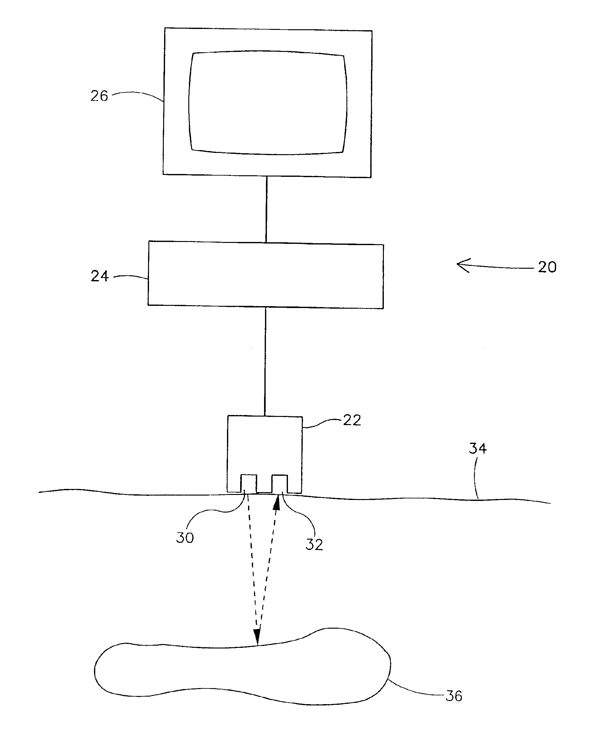
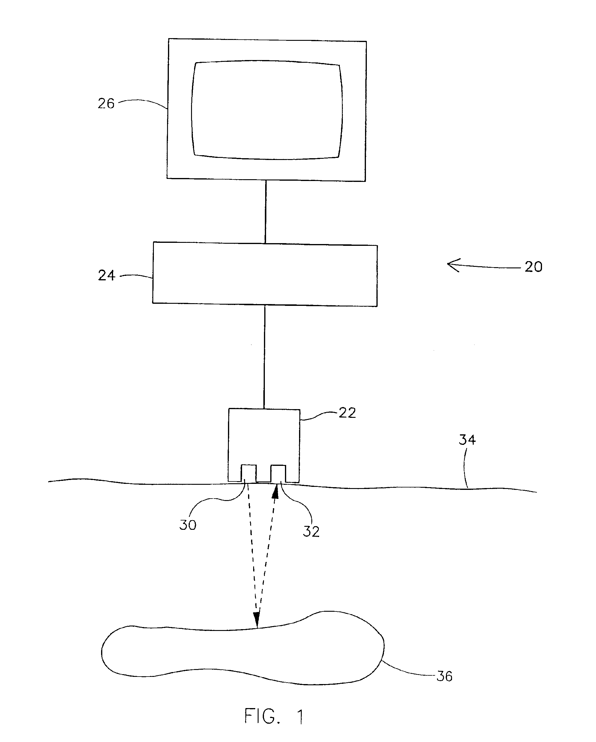
[0020]Referring now to the drawings and in particular to FIG. 1, apparatus of the present invention for ultrasonic imaging is designated in its entirety by the reference numeral 20. The apparatus 20 generally comprises a transducer 22 operatively connected to a control and processor unit 24 connected to a display 26. The transducer 22 includes elements 30, 32 arranged in an array that emit and receive ultrasonic energy, respectively, under the control of the control and processor unit 24. As will be appreciated by those skilled in the art, in most implementations of the present invention each element 30, 32 of the transducer 22 both emits and receives energy. The elements are numbered 30 and 32 for convenience in describing the path of energy to and from the transducer 22. Although the transducer 22 may include fewer or more transmitting and receiving elements 30, 32 without departing from the scope of the present invention, in one embodiment the transducer includes between about 20...


PUM


Abstract

A method for reducing speckle in an ultrasonic image formed from a digitized scan line including linearly arranged signal intensity data points obtained from ultrasonic energy reflected by structures within a body. The scan line is divided into intensity pixels. Each intensity pixel includes at least one data point. A raw intensity level and a feature gain factor are determined for each intensity pixel. A corrected intensity level is calculated for each intensity pixel by multiplying the raw intensity level for each intensity pixel by the corresponding feature gain factor. The corrected intensity level of each intensity pixel is displayed.

Description

BACKGROUND OF THE INVENTION[0001]The present invention relates generally to ultrasonic imaging, and more particularly to a technique for increasing a signal-to-noise ratio and reducing speckle in ultrasonic images used for making medical diagnoses.[0002]Ultrasonic imaging, which is used to provide visual representations of tissues in patients so medical personnel may make appropriate diagnoses, is performed using apparatus including a transducer having elements that emit ultrasonic energy into the body of a patient. The energy is reflected by tissue in the body and the reflected energy is converted to an electrical signal by other elements in the transducer. The intensity of the electrical signal varies with the characteristics of the tissue. The elements in the transducer are typically arranged in an array and the output from the elements is displayed as an image on a video monitor.[0003]The usefulness of ultrasonic imaging is somewhat limited by a low signal-to-noise ratio in the ...

Claims


Application Information

Patent Timeline
Patent Type & Authority Patents(United States)
IPC IPC(8): G01S15/89G01S15/00G01S7/52G06T5/00
CPCG01S7/52077G01S15/8977G06T5/10G06T5/008G06T2207/10132G06T2207/30004
Inventor HASTINGS, HAROLD M.EVANS, STEVEN J. L.ROTH, SCOTT L.
Owner IMACOR INC
Why Eureka
Try Eureka