Temporal thermometer disposable cap

a technology of thermometers and caps, which is applied in the field of infrared thermometers, can solve the problems of large temperature change at the artery and inaccessible at the skin, and achieve the effect of convenient temperature readings

Inactive Publication Date: 2005-08-23
EXERGEN CORPORATION
View PDF54 Cites 25 Cited by
  • Summary
  • Abstract
  • Description
  • Claims
  • Application Information

AI Technical Summary

Benefits of technology

[0012]Demonstrably, the temporal artery is very easily accessible; in fact in most individuals, it is usually quite visible. Terminating in a two-prong fork, it easily doubles the assurance of measuring the correct area. Touching it does not present a risk of injury. There are no mucous membranes present, thus eliminating the risk of contaminates such as those found in the mouth and rectum. And, despite lying so close to the skin surface, the temporal artery perfusion, which is the flow of blood per unit volume of tissue, remains relatively constant and so ensures the stability of blood flow required for our measurement.
[0013]A temporal artery detector that employs a temperature sensor that is scanned across the forehead is disclosed in U.S. patent application Ser. No. 09 / 151,482, the contents of which are incorporated herein by reference. Although the cross-contamination problem is still obviated through use of disposable plastic sheets positioned over the sensor, it has been found that the condensation problem associated with moisture from the skin, as described in the '419 Pompei patent, is outweighed by inherent problems associated with the transparent film used to prevent the moisture from condensing adjacent the temperature sensor. This is attributable to at least two factors. First, the forehead region is less prone to moisture perfusion and thus the associated problems are less prevalent. Second, because the detector is dynamically scanned across the forehead, the transparent film may lift from the skin surface which induces inaccuracies in the resulting temperature reading. It is has been found that discarding this film increases the accuracy of the temperature readings.
[0018]According to a further aspects, the flange includes an inside surface and an outside surface and a radius of curvature adjacent the viewing end such that an outer periphery of the inside surface of the flange contacts the terminal end of the detector to provide an air gap between the terminal end of the detector and the flange. The air gap insulates the end of the detector from the target surface to minimize inaccurate temperature readings. The air gap also serves as a cushion to reduce any uncomfortableness associated with pressing the detector too hard against the target surface.
[0022]A method of detecting human body temperature is provided which includes the steps of providing a temperature detector which includes a metal end, such as stainless steel or other suitable material, which is positioned adjacent the body during temperature detection. Substantially all of the end of the detector likely to contact the body is covered with a disposable cap. The end of the detector is moved across the skin of the body to detect the body temperature, the detector being moved at the rate of about 1 inch / second, wherein the cap cools the surface of the skin by less than about 0.2° Fahrenheit. This helps insure a reliable temperature reading.
[0024]Preferably, electronics in the detector detect the maximum peak temperature of the two scans. Also, it is preferable that the operator continuously scan the detector from the forehead to behind the ear. A disposable cap, as described above, can cover the end of the temperature detector to prevent cross-contamination between persons.

Problems solved by technology

This can result in a large temperature change at the artery which is a local artifact only and not representative of core temperature.
But the carotids, even the external carotid, are at best partially embedded, and at worst completely embedded in the skull, and therefore are not accessible at the skin.

Method used


Image

  • Temporal thermometer disposable cap
  • Temporal thermometer disposable cap
  • Temporal thermometer disposable cap

Examples


Embodiment Construction

[0034]As illustrated in FIG. 1, the temporal arteries 12 and 14 extend upwardly toward the side of the human face and bifurcate at 16 and 18 in the forehead region. In that region, the temporal artery passes over the skull bone very close to the skin and is thus termed the superficial temporal artery. The superficial temporal artery is, therefore, particularly accessible for providing temperature readings and, as an artery, has a temperature close to the heart temperature. Further, there are no known arterial / venus anastomoses, that is, shunts between the artery and veins for regulation of skin temperature. Accordingly, the blood flow is relatively stable, varying very little compared to other areas of the skin.

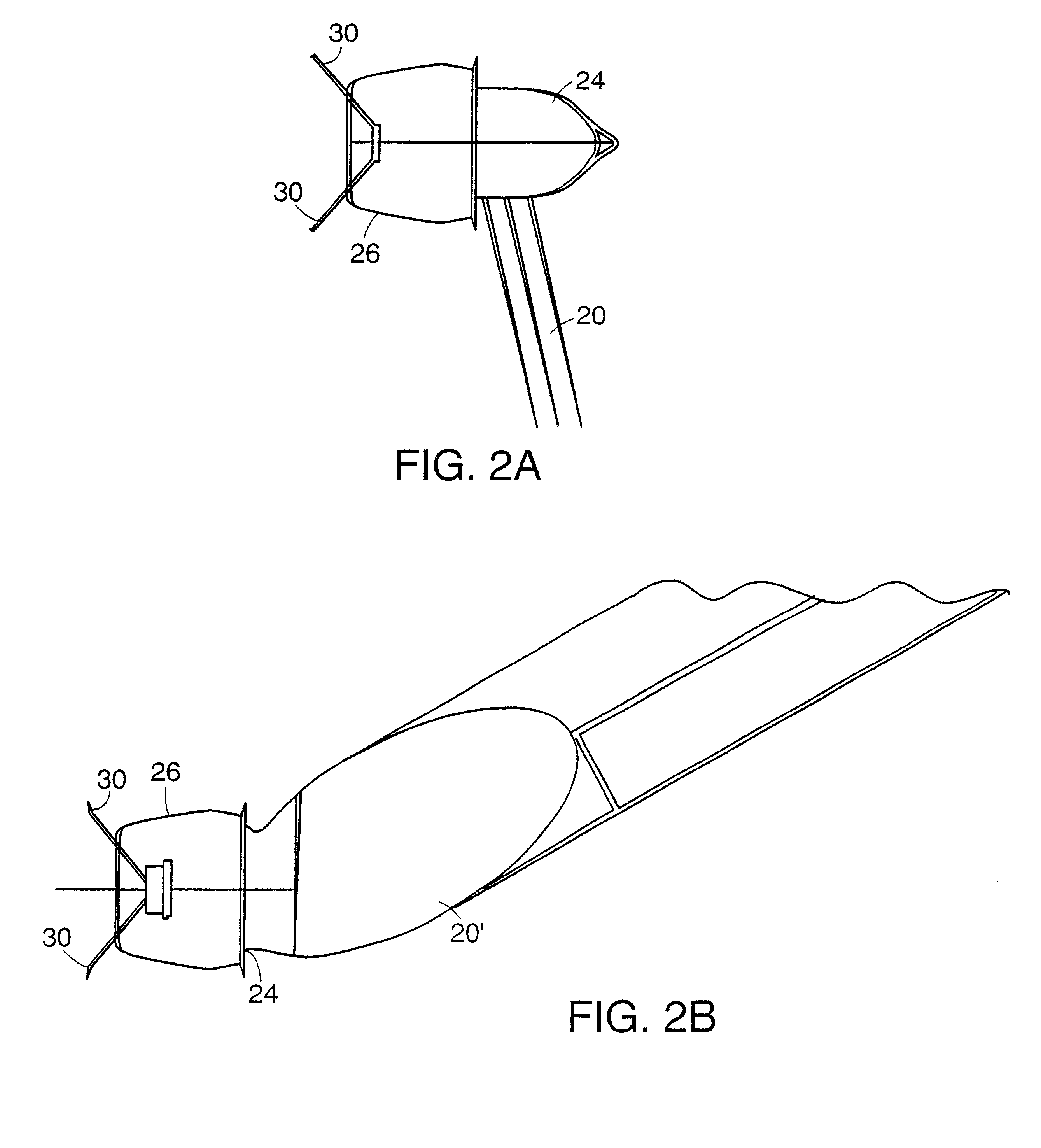
[0035]To locate the temporal artery, a temperature sensor, preferably a radiation temperature detector 20, is scanned across the side of the forehead over the temporal artery while electronics in the detector search for the peak reading which indicates the temporal artery. Pr...


PUM

PropertyMeasurementUnit
thicknessaaaaaaaaaa
diameteraaaaaaaaaa
diameteraaaaaaaaaa

Abstract

A disposable cap for a body temperature detector includes a body having a viewing end and a retaining end. The retaining end includes an inward protrusion that expands over a wider portion of an end of the detector and contracts after the retaining end has passed over the wider portion to snugly secure the cap on the detector. The cap further includes a flange with an aperture therethrough adjacent the viewing end to permit a radiation sensor of the detector to view a target surface. Preferably, the cap is sufficiently large so as to not be insertable into an ear of a human. The cap is formed from a sheet of material, preferably by thermoforming, from a material such as polypropylene, polyethylene, polystyrene, or other similar material which has relatively low hardness and low thermal conductivity properties. The cap has a generally uniform thickness of about 0.020 inch.

Description

RELATED APPLICATION[0001]This application is a divisional application of application Ser. No. 09 / 448,909, filed Nov. 24, 1999 now U.S. Pat. No. 6,319,206, the entire teachings of which are incorporated herein by reference.BACKGROUND OF THE INVENTION[0002]In recent years, infrared thermometers have come into wide use for detection of temperature of adults. For core temperature readings, infrared thermometers which are adapted to be inserted into the patient's ear have been very successful. Early infrared thermometers were adapted to extend into the ear canal in order to view the tympanic membrane and provide an uncorrected, direct reading of tympanic temperature which correlates with pulmonary artery temperature. More recently, however, to provide for greater comfort and ease of use, ear thermometers have been designed to provide corrected readings of the generally cooler distal ear canal. Such thermometers measure temperature of distal ear canal tissue and calculate arterial core te...

Claims


Application Information

Patent Timeline
Patent Type & Authority Patents(United States)
IPC IPC(8): G01K13/00A61B5/01G01J5/02G01J5/04
CPCG01J5/0022G01J5/0025G01J5/02G01J5/021G01J5/025G01J5/026G01J5/04G01J5/046G01J5/08G01J5/089G01J5/07
Inventor POMPEI, FRANCESCOPOMPEI, MARYBETH A.
Owner EXERGEN CORPORATION
Why Eureka
Try Eureka