Pressure measuring arrangement

a technology of pressure measurement and arrangement, applied in the direction of fluid pressure measurement by electric/magnetic elements, measuring devices, instruments, etc., can solve the problem of not always usable compact design

Inactive Publication Date: 2005-08-30
EHNDRESS KHAUZER GMBKH KO KG
View PDF20 Cites 5 Cited by
  • Summary
  • Abstract
  • Description
  • Claims
  • Application Information

AI Technical Summary

Benefits of technology

[0020]a pressure screw, through which screw the pressure line is passed and is secured there by means of a mount disposed on a side of the pressure screw oriented toward the base body, and which screw has a thread

Problems solved by technology

Since the filling is comparatively complicated and requires special operating media, a measuring ar

Method used


Image

  • Pressure measuring arrangement
  • Pressure measuring arrangement
  • Pressure measuring arrangement

Examples


Embodiment Construction

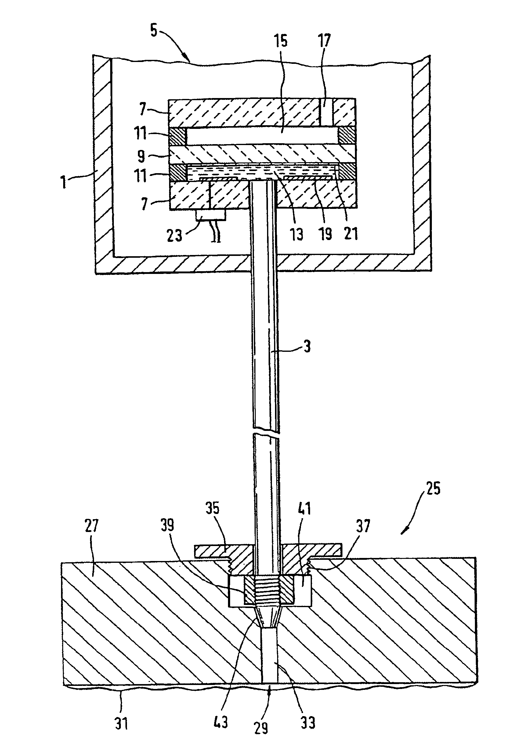
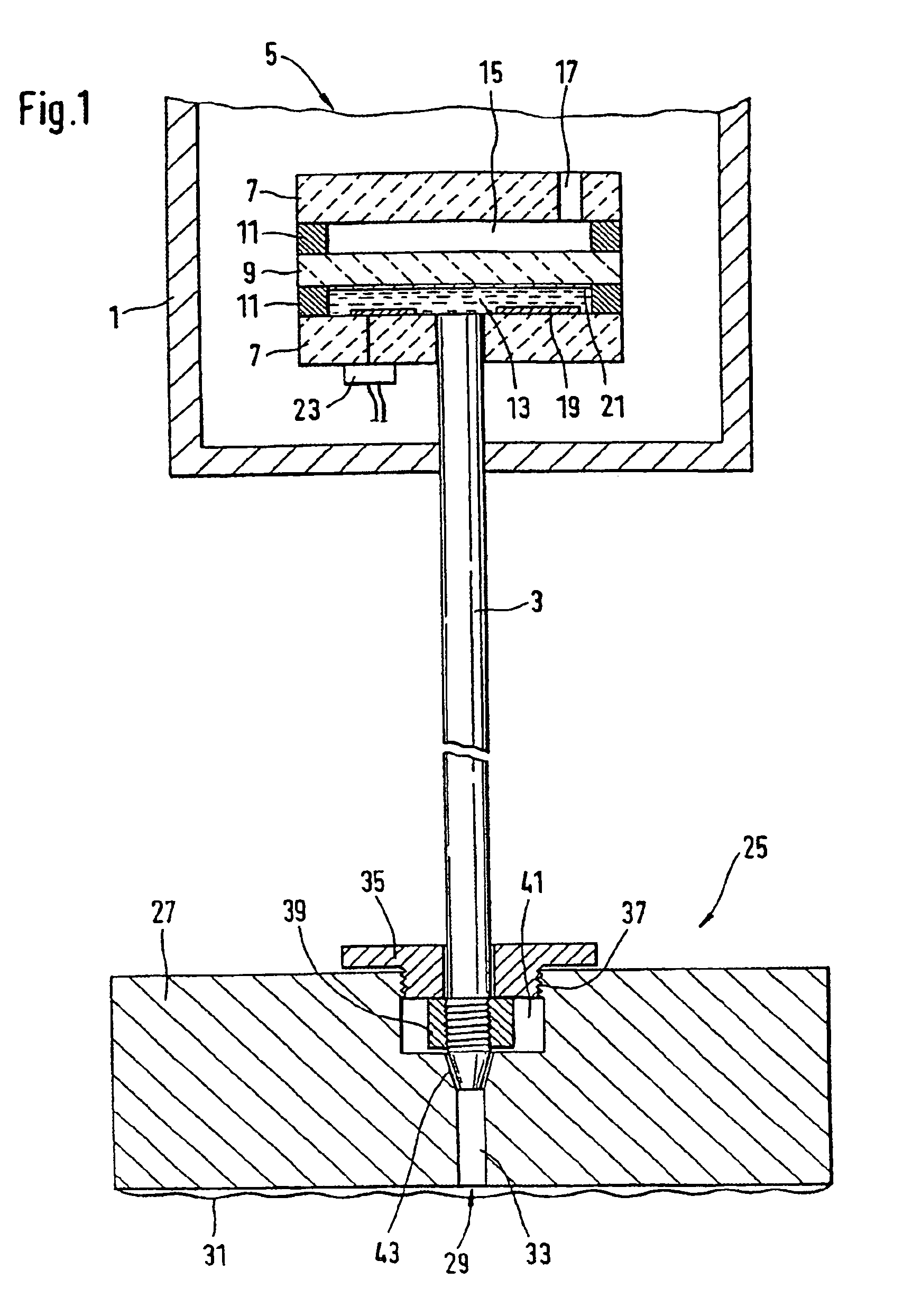
[0037]FIG. 1 shows a section through a pressure measuring arrangement of the invention. It has a capacitive ceramic pressure measuring cell, in this case a relative-pressure measuring cell, that is soldered onto a pressure tube 3 in a manner free from fastening in a housing 1.

[0038]The pressure measuring cell 5 includes two ceramic base bodies 7, between which a membrane 9 is disposed. The membrane 9 is connected by means of two annular joining points 11 to the base bodies 7, forming a first and a second chamber 13, 15. The first chamber 13 communicates with the pressure tube 3 via a bore in the base body 7. In the exemplary embodiment shown, the pressure tube 3 is soldered into the bore in the base body 7. By way of the pressure tube 3, the pressure measuring cell 5 is supplied with a pressure corresponding to a pressure to be measured.

[0039]To that end, the first chamber 13 and the pressure tube 3 are filled with a substantially incompressible fluid, such as a silicone oil, that i...


PUM


Abstract

The invention relates to a pressure measuring arrangement comprising a pressure measuring cell which is fed by a pressure corresponding to the pressure which is to be measured by a pressure tube filled by a pressurised liquid; at least one pressure recording unit is arranged separately from said cell, said unit being impinged upon by a pressure which is to be measured during operation, producing a pressure corresponding to the pressure which is to be measured via a pressure line filled by a liquid; a connection between the pressure tube and the pressure line. A modular design and a large amount of flexibility is obtained in respect of the spatial arrangement of the pressure measuring cell and the pressure recording unit. The connection consists of a base body wherein at least one end section of the pressure line is arranged, in addition to a pressure screw through which the pressure tube passes and is secured by a fixing element arranged on a side which is oriented towards the base body of the pressure screw. Said pressure screw has a thread which enables it to be screwed onto base body in such a way that the pressure tube and the pressure line are connected, and the connection is effectively sealed between the pressure tube and the pressure line.

Description

FIELD OF THE INVENTION[0001]The present invention relates to a pressure measuring arrangement with a pressure measuring cell and a pressure recording unit, in which in operation a pressure to be measured acts on the pressure recording unit and is converted into a pressure corresponding to the pressure to be measured, which converted pressure is delivered via a fluid-filled connection from the pressure recorder to the pressure measuring cell of the pressure measuring cell.BACKGROUND OF THE INVENTION[0002]Such pressure measuring arrangements are used if a pressure to be measured cannot be delivered directly to the pressure measuring cell. This is the case for instance whenever the pressure measuring cell is very vulnerable to chemical and / or mechanical stresses, as is the case for instance with piezoresistive pressure measuring cells that for instance have measuring membranes comprising or having vulnerable semiconductor components, or if a difference between two pressures that act at...

Claims


Application Information

Patent Timeline
IPC IPC(8): G01L9/00G01L19/00G01L9/12
CPCG01L9/0075G01L19/0046
Inventor BANHOLZER, KARL-HEINZFLOGEL, KARLHEGNER, FRANKROSSKOPF, BERND
Owner EHNDRESS KHAUZER GMBKH KO KG
Why Eureka
Try Eureka