Method and system for carrier recovery

a carrier recovery and carrier technology, applied in the field of carrier recovery, can solve the problems of inability to achieve carrier acquisition scheme stability, inability to recover digital complex baseband signals from analog-to-digital converters, pipeline delays,

Inactive Publication Date: 2005-08-30
SPACEBRIDGE SEMICON CORP
View PDF5 Cites 16 Cited by
  • Summary
  • Abstract
  • Description
  • Claims
  • Application Information

AI Technical Summary

Benefits of technology

[0007]It is an object of the present invention to obviate or mitigate at least one disadvan

Problems solved by technology

In modem digital receivers, the digital complex baseband signal recovered from the analog-to-digital converter invariably contains residual carrier frequency errors due to mismatches between the transmit and receive local oscillators.
Each hardware multiplication and addition operation in the carrier recovery feedback loop 20 will therefore introduce pipeline

Method used


Image

  • Method and system for carrier recovery
  • Method and system for carrier recovery
  • Method and system for carrier recovery

Examples


Embodiment Construction

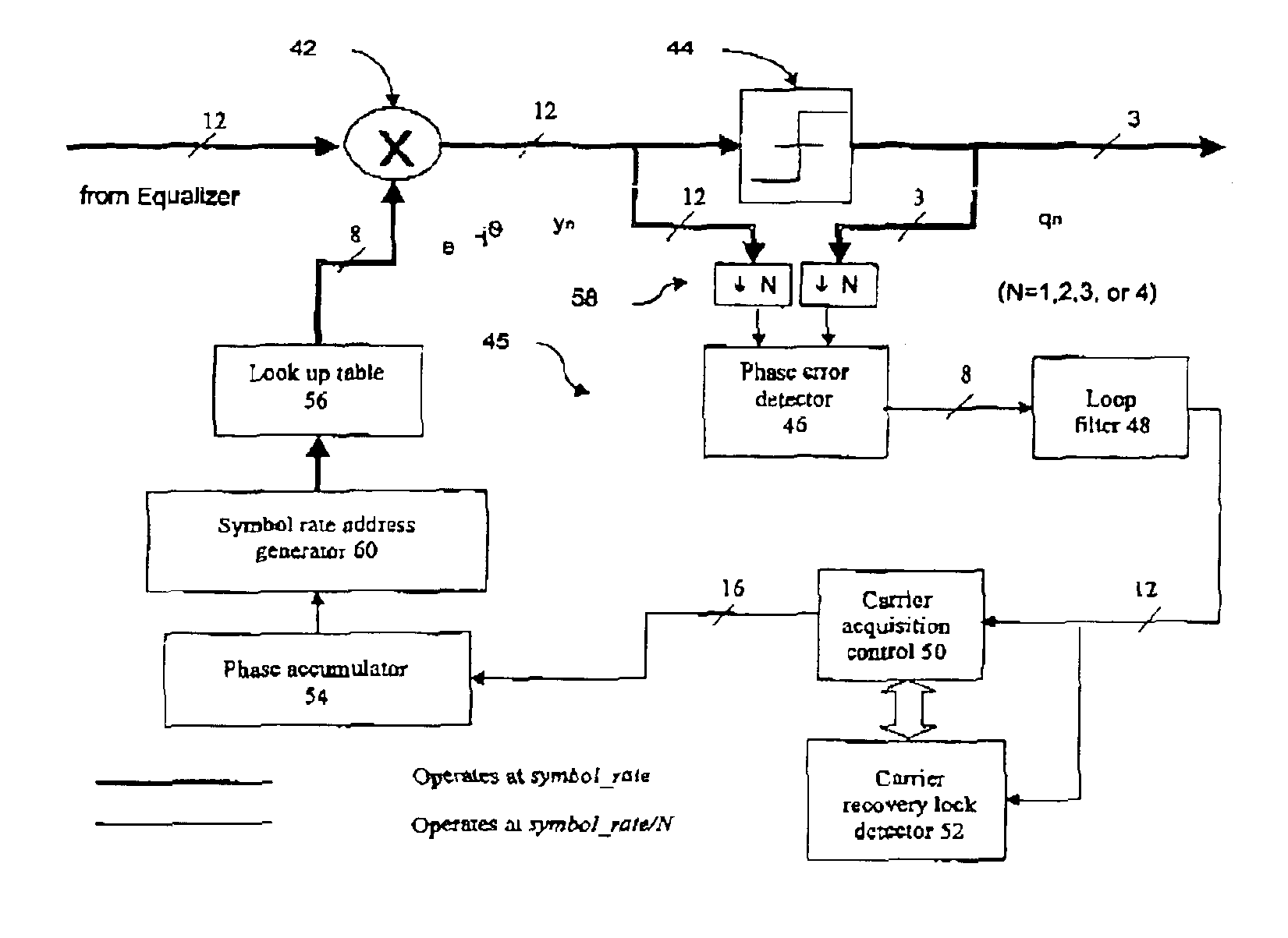
[0022]Referring to FIG. 4, a carrier recovery system 40 according to the present invention is shown. The carrier recovery loop forms part of a high data rate digital demodulator, or digital receiver, and compensates for carrier frequency errors due to mismatches between transmit and receive local oscillators. Typically, the carrier recovery loop 40 operates in conjunction with an equalizer (not shown), from which it receives a filtered signal. The resulting compensated signal is provided to timing recovery and IQ generator modules (not shown) for further processing.

[0023]The carrier recovery system 40 consists of a phase derotator 42, a slicer 44, and a feedback loop 45 having a phase error detector 46, a loop filter 48, a carrier acquisition control 50 communicating with a carrier recovery lock detector 52, a phase accumulator 54, and a sine cosine look-up table 56, as in previously known carrier recovery loops. In addition, the carrier recovery loop 40 includes down-sampling means...


PUM


Abstract

A method and sytem for achieving carrier frequency synchronization in a high speed receiver. A feedback loop in a carrier recovery system is operated at a down-sampled rate until carrier lock is detected. The output of a phase accumulator, operating at the down-sampled rate, is then extrapolated to provide extrapolated outputs to provide outputs at the original symbol rate. Addresses for a look-up table are then generated from the combined phase accumulator outputs and extrapolated outputs, such that the frequency and phase compensation offsets provided to a phase derotator and slicer are at the original symbol rate. The total pipeline delay as seen by the carrier recovery system is thus reduced. This in turn allows for more efficient correction of residual carrier frequency errors present in a complex baseband signal.

Description

FIELD OF THE INVENTION[0001]The present invention relates to a method and system for achieving carrier frequency synchronization in a high speed receiver. In particular, the present invention relates to the carrier recovery loop in a high-speed digital demodulator that compensates for the phase and frequency offsets that are present in the complex baseband signal recovered from the receiver.BACKGROUND OF THE INVENTION[0002]In modem digital receivers, the digital complex baseband signal recovered from the analog-to-digital converter invariably contains residual carrier frequency errors due to mismatches between the transmit and receive local oscillators. These residual carrier errors must be removed before the baseband signal can be further processed and outputted. One system for correcting this residual carrier error uses a carrier recovery loop circuit that provides compensating feedback phase and frequency offsets to the corrupted complex baseband signal. FIG. 1 illustrates the in...

Claims


Application Information

Patent Timeline
IPC IPC(8): H04L27/00
CPCH04L27/0014H04L2027/0028H04L2027/0036H04L2027/0053
Inventor SAMARASOORIYA, VAJIRA N. S.
Owner SPACEBRIDGE SEMICON CORP
Why Eureka
Try Eureka