Electrical connector with anti-mismating arrangement

a technology of anti-mismation and connector, applied in the direction of coupling contact member, coupling device connection, printed circuit, etc., can solve the problems of irreliable electrical connection, mismatch in assembly, electrical connection mistakes, etc., to prevent the camera module from shaking and avoid assembly mistakes

Inactive Publication Date: 2005-09-06
HON HAI PRECISION IND CO LTD
View PDF7 Cites 63 Cited by
  • Summary
  • Abstract
  • Description
  • Claims
  • Application Information

AI Technical Summary

Benefits of technology

[0010]To compare with the conventional invention, the merit of this invention is the projecting portion. The projecting portion engages with the cutout. Because of the only one projecting portion and the only one cutout correspondingly defined in the shield, the projecting portion is deemed to engage with the cutout in a predetermined way. Such a design can avoid mistakes in assembly thus ensuring a function of anti-mismatch. In another hand, the projecting portion can also prevent the camera module from shaking.

Problems solved by technology

So, the lens barrel may be inserted in any directions, which may result in a mismatch in assembly and cause mistakes in electrical connections in farther.
However, the electrical connector 100′ has not any anti-mismating designs either, which may cause an incorrect assembly, too.
This may cause irreliable electrical connections.

Method used


Image

  • Electrical connector with anti-mismating arrangement
  • Electrical connector with anti-mismating arrangement
  • Electrical connector with anti-mismating arrangement

Examples


Embodiment Construction

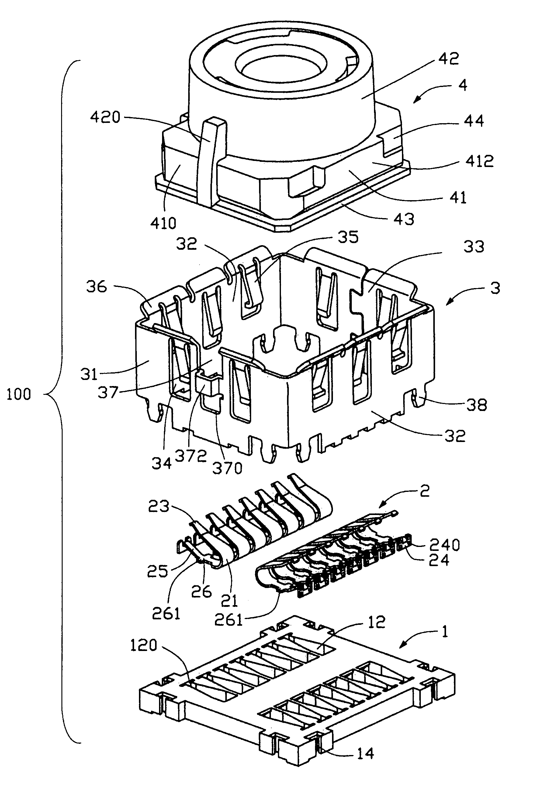
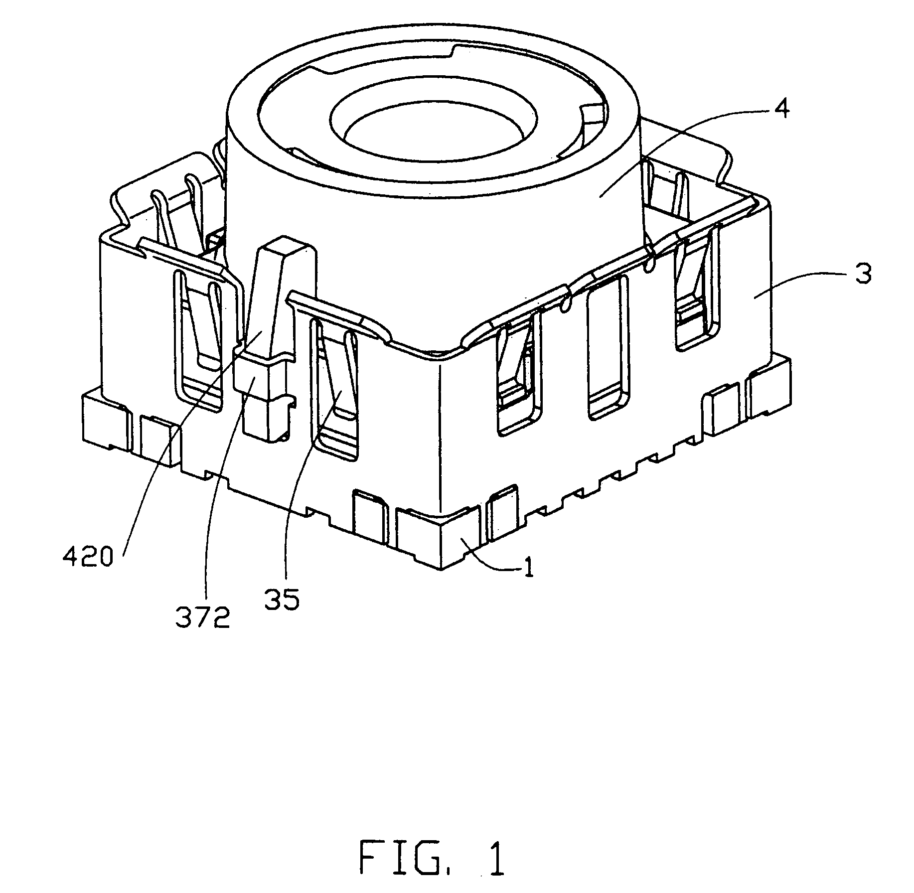
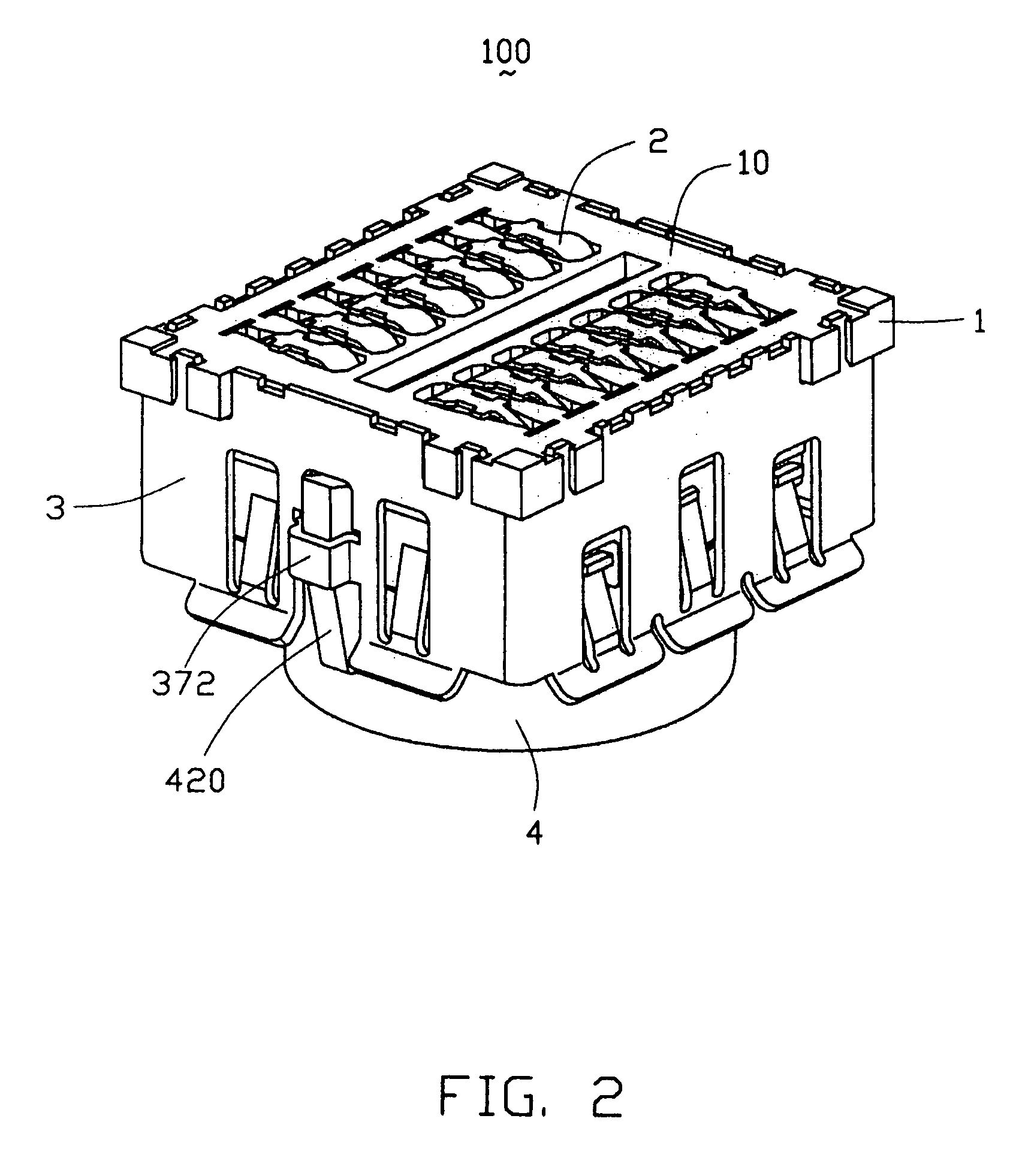
[0019]Referring to FIGS. 3 and 4, an electrical connector 100 in according with the present invention comprises an insulative housing 1, a plurality of contacts 2, a shield 3 and a camera module 4 (an electrical element).

[0020]The insulative housing 1 defines a plurality of passageways 12 symmetrically arranged in two rows in the longitudinal direction. A slit 120 is defined in the traverse direction adjacent one of each passageway 12 and communicating with the passageway 12. The insulative housing 1 also comprises a plurality of engaging slots 14 at corner portions and a bottom surface 10 at a lower surface thereof.

[0021]Each contact 2 is made of conductive material, and is formed with a U-shaped holding portion 24. The holding portion 24 has a plurality of semi-spherical protrusions 240 projecting from a side face (not labeled) thereof. An extending portion 25 laterally extends from a central part of the U-shaped the holding portion 24. A soldering portion 26 extends from one end ...


PUM


Abstract

An electrical connector (100) includes an insulative housing (1), a number of contacts (2), a shield (3) and a camera module (4). The insulative housing has a number of passageways (12) defined therein. The contacts are correspondingly received in the passageways. Each contact includes a holding portion (24) engaging with the passageway and securing the contact with the housing, a soldering portion (26) soldering to a Printed Circuit Board, and a contacting portion (23) electrically connecting the camera modules The camera module mounts on the insulative housing, and have a number of contacting sections (430). The camera module also defines a number of hook engaging portions (44), and a projecting portion (420). The shield has a number of hooking portions (35) corresponding to the hook engaging portions and a cutout (37) engaging with the projecting portion. The shield surfacely and peripherally surrounds the camera module.

Description

BACKGROUND OF THE INVENTION[0001]1. Field of the Invention[0002]The present invention relates to an electrical connector, particularly to an electrical connector applied in the mobile phones or other electronic equipments.[0003]2. Description of the Prior Art[0004]A conventional electrical connector is described in the U.S. Pat. No. 6,243,540. The conventional electrical connector comprises a lens barrel and a lens hood detachably mounted on the lens barrel. The lens barrel is formed with a first outer circumference portion. The first outer circumference portion has three projected guide rails symmetrically provided thereon. The lens hood correspondingly defines three groove notches. The groove notches each engages with the corresponding guide rail thereby securing the lens barrel with the lens hood.[0005]As is described above, the guide rails are formed symmetrically on the first outer circumference, and the electrical connector has not any anti-mismating designs. So, the lens barr...

Claims


Application Information

Patent Timeline
Patent Type & Authority Patents(United States)
IPC IPC(8): H01R13/658H01R13/24H01R13/22
CPCH01R13/65802H01R12/716H01R13/24H01R12/714H01R13/6582
Inventor LU, YAO PANG
Owner HON HAI PRECISION IND CO LTD
Why Eureka
Try Eureka