
Computerized interactor systems and methods for providing same

a technology of interactors and interactors, applied in the field of human/computer interfaces, can solve the problems of increasing the difficulty of human/machine interfaces, and affecting the quality of human/computer interfaces, so as to improve the human-computer interface

Inactive Publication Date: 2005-09-06
HANGER SOLUTIONS LLC
View PDF72 Cites 15 Cited by
  • Summary
  • Abstract
  • Description
  • Claims
  • Application Information

AI Technical Summary

Benefits of technology

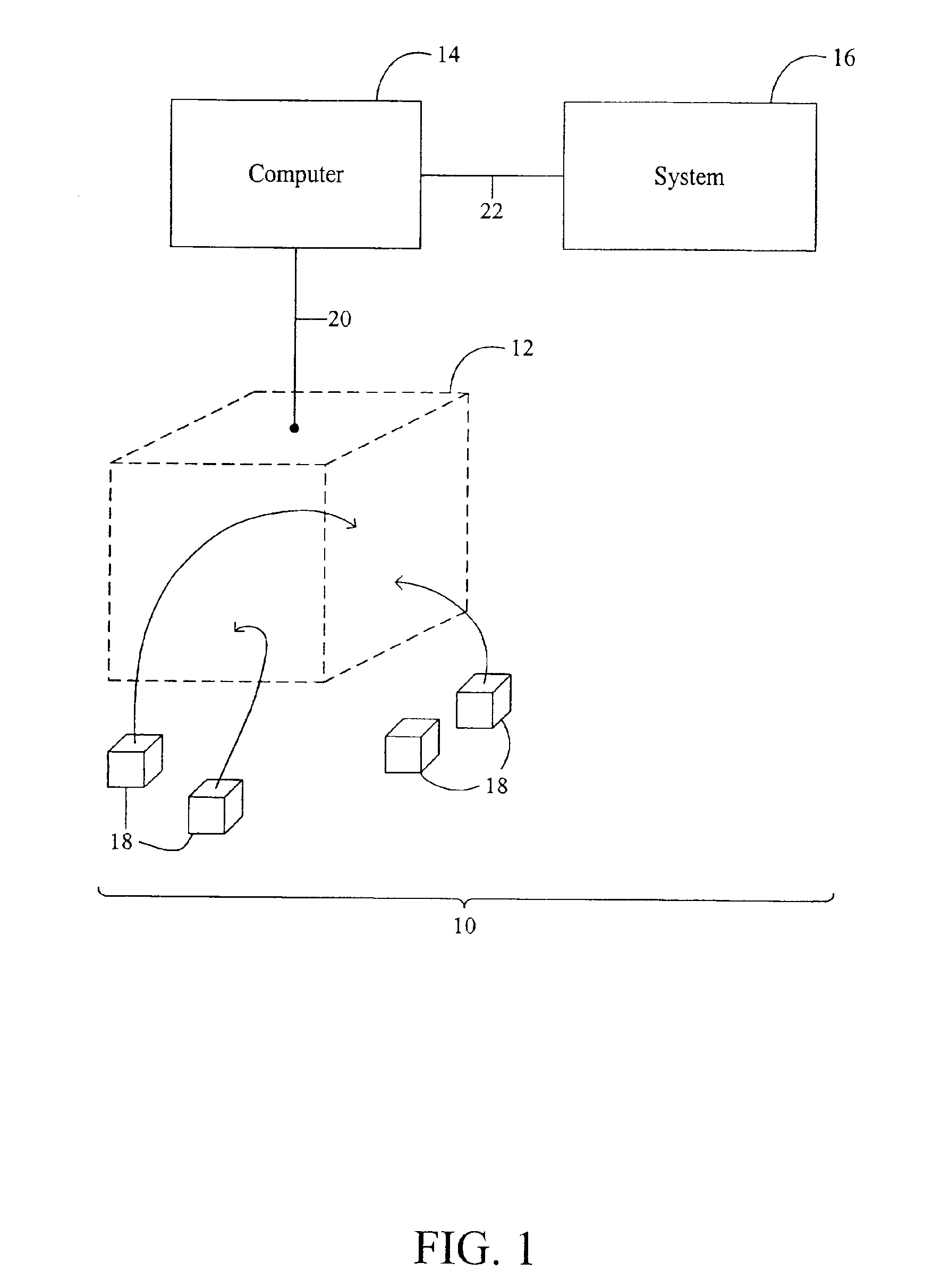
[0011]The present invention improves the human-computer interface by using “interactors.” An interface couples a detection field to a controller computer system which, in turn, may be coupled to other systems. When an interactor is entered into the detection field, moved about within the detection field, or removed from the detection field, an event is detected which, when communicated to the computer system, can be used to create a control signal for either the controller computer system or to a system connected to the controller computer system. Preferably, the detection field is suitably sized and configured so that multiple users can simultaneously access the field and such that multiple interactors can be engaged with the field simultaneously.
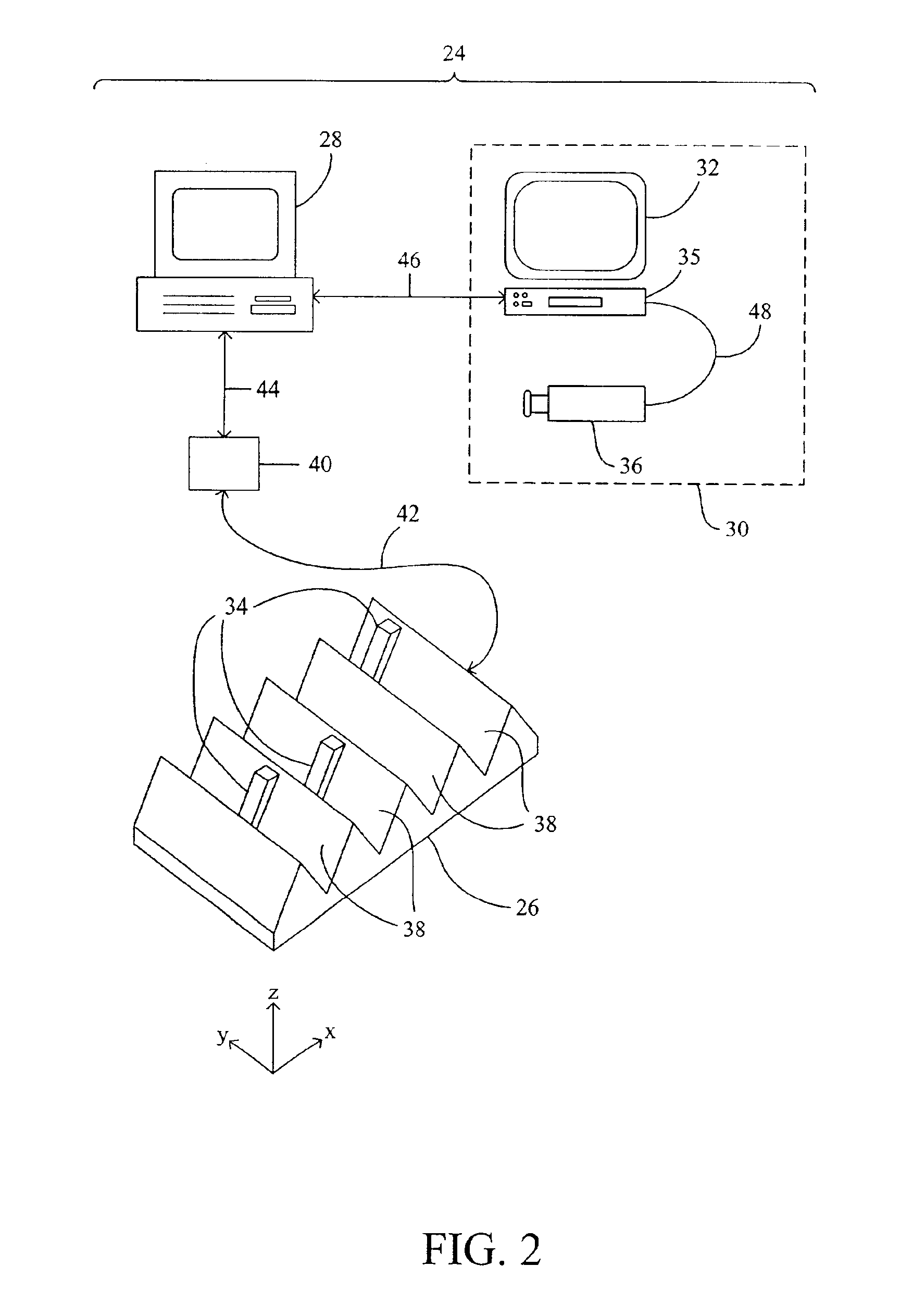
[0017]In the second example, a videotape “marking” system is described. A videotape player is coupled to a controlling computer, and a videotape is played and observed by one or more users on a monitor. When an event occurring on the videotape is to be logged or marked, an interactor is engaged with the detection field. The controlling computer then retrieves timing information from the videotape player and combines this with the marking event. Removal of the interactor from the detection field can signify the end of the event, or can signify nothing, depending upon the context and the desires of the users. The detection field is preferably sized and configured so that multiple viewers of the video playback can simultaneously access the detection field. By taking a group approach, each individual can be watching for and marking a specific event or a small group of events. This approach can reduce the fatigue and tedium with logging videotape.
[0018]By using interactors, the human / computer interface is greatly enhanced. In the example of the audio control system, it takes little or no training to use the system since the interactors and their spatial relationships are intuitive to the user. Likewise, it is a very physically intuitive gesture for a user to place a labeled or otherwise evocative interactor on a detection field in response to a certain event detected in a video playback. The present invention therefore provides a more intuitive and richer metaphor for the interaction between humans and computerized systems. Furthermore, the present invention provides a system whereby multiple users simultaneously communicate with a computerized system using the metaphor.

Problems solved by technology

However, the price that must be paid for this power and flexibility is, typically, an increase in the difficulty of the human / machine interface.
However, these human / computer interfaces are quite artificial in nature, and tend to require a substantial investment in training to be used efficiently.
While GUIs are a major advance in human / computer interfaces, they nonetheless present a user with a learning curve due to their still limited metaphor.

Method used


Image

  • Computerized interactor systems and methods for providing same
  • Computerized interactor systems and methods for providing same
  • Computerized interactor systems and methods for providing same

Examples


example 1

An Audio Control System

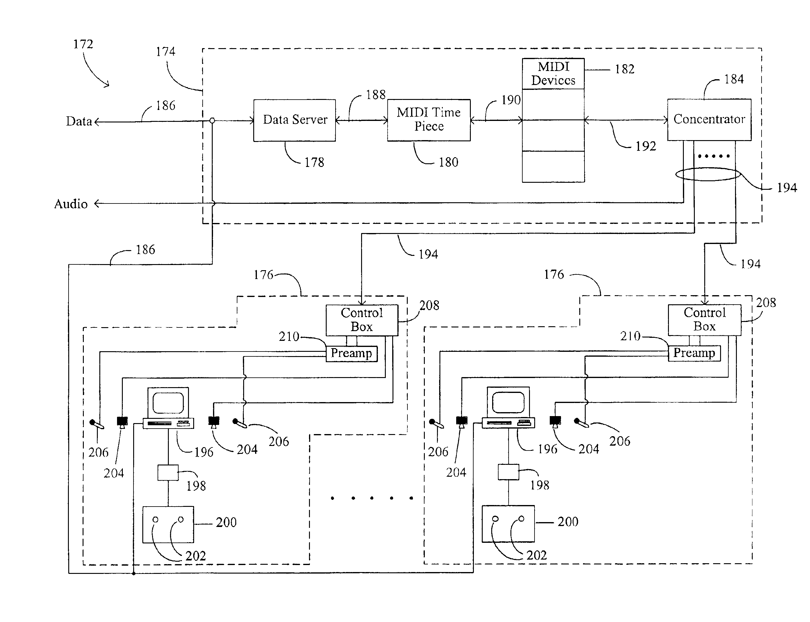
[0073]In FIG. 10, an interactor 152 is shown which will be used for a particular implementation of the present invention. The interactor 152 includes a body 154 that operates functionally in a fashion very similar to that of the interactor 34 illustrated in FIGS. 5 and 5a. The interactor 152 can be used with a detection field similar to or identical with detection field 26 as illustrated in FIGS. 3, 4, and 6. The detection field 26 used with the interactor 152 can also use the same interface 40 to interconnect the field with a computer system 28.

[0074]The difference between interactor 152 and the previously described interactor 34 is therefore design related and not computational in nature in that they support different metaphors. With the interactor 152, a doll's head 156 or other talisman is provided with a peg 158 which can engage a hole 160 in the body 154. A small piece of white board 162 is removably attached to the body 154 by a pair of hook-and-pile (e...

example 2

Videotape Marking System

[0091]In this second example, an interactor system such as interactor system 24 is controlled to “mark” or “log” events in a videotape. In FIG. 17, a detection field 298 includes three zones 300a, 300b, 300c and a number of interactors 302. Each of the interactors has a semantic meaning due to its identity, due to their position in the various zones 300a, 300b, and 300c of the detection field 298, and due to their amount or “type” of time they have been present in the detection field (up / down or, as sometimes referred to herein, exit / enter). The various objects 302 can be used mark and control the temporal flow of a recorded medium as described previously with regards to FIG. 2.

[0092]As used herein, “temporal flow” will refer to the flow of events, either in real time or in some other time related context. Therefore, either events can be marked in a temporal flow, or events that have been previously recorded or that are being concurrently recorded can be mark...


PUM


Abstract

A computerized interactor system uses physical, three-dimensional objects as metaphors for input of user intent to a computer system. When one or more interactors are engaged with a detection field, the detection field reads an identifier associated with the object and communicates the identifier to a computer system. The computer system determines the meaning of the interactor based upon its identifier and upon a semantic context in which the computer system is operating. The interactors can be used to control other systems, such as audio systems, or it can be used as intuitive inputs into a computer system for such purposes as marking events in a temporal flow. The interactors, as a minimum, communicate their identity, but may also be more sophisticated in that they can communicate additional processed or unprocessed data, i.e. they can include their own data processors. The detection field can be one-dimensional or multi-dimensional, and typically has different semantic meanings associated with different parts of the detection field.

Description

CROSS-REFERENCE TO RELATED APPLICATION[0001]This is a Divisional application of copending prior application Ser. No. 08 / 801,085 filed on Feb. 14, 1997 now U.S. Pat. No. 6,262,711.[0002]This application claims the benefit of copending U.S. patent application Ser. No. 08 / 692,830, filed Jul. 29, 1996, which claims the benefit of U.S. Provisional Patent Application No. 60 / 001,875, entitled “Computerized Interactor Systems And Methods For Providing Same,” filed Aug. 3, 1995, each of which is incorporated herein by reference in its entirety.BACKGROUND OF THE INVENTION[0003]This invention relates generally to human / computer interfaces and more particularly to mechanical input devices for computerized systems.[0004]It has become increasingly common to computerize systems, from the trivial (e.g., the computerized toaster or coffee pot) to the exceedingly complex (e.g., complicated telecommunications and digital network systems). The advantage of computerization is that such systems become mo...

Claims


Application Information

Patent Timeline
Patent Type & Authority Patents(United States)
IPC IPC(8): G06F3/00G06F3/033H04M3/56G06F3/01
CPCG06F3/011G06F3/033G06F3/0354H04M3/567
Inventor COHEN, JONATHAN R.HINDUS, DEBBYJOHNSON, BONNIE M.SINGER, ANDREW J.STIFELMAN, LISA J.VERPLANK, WILLIAM L.WALLTERS, SCOTT C.WITHGOTT, M. MARGARET
Owner HANGER SOLUTIONS LLC
Learn More