Image forming apparatus having rotary unit for holding multiple developing devices

a technology of developing device and forming apparatus, which is applied in the direction of electrographic process apparatus, instruments, optics, etc., can solve the problems of inability to complete the removal of the blade print, inability to perform image forming, and increased power consumption in the standby state, so as to achieve the effect of suppressing uneven densities of images

Inactive Publication Date: 2005-09-06
CANON KK
View PDF11 Cites 4 Cited by
  • Summary
  • Abstract
  • Description
  • Claims
  • Application Information

AI Technical Summary

Benefits of technology

[0008]To resolve the above shortcomings, it is one objective of the present invention to provide an image forming apparatus that can suppress uneven densities in an image.

Problems solved by technology

When the preparative rotation of a developing roller is performed immediately before the developing, the period before the developing process is started is too short, and complete removal of a blade print can not be expected.
Further, if rotation of the developing roller occurs after a predetermined time has elapsed following termination of the image forming, power consumption in the standby state, wherein image forming is not performed, will be increased.

Method used


Image

  • Image forming apparatus having rotary unit for holding multiple developing devices
  • Image forming apparatus having rotary unit for holding multiple developing devices
  • Image forming apparatus having rotary unit for holding multiple developing devices

Examples


Embodiment Construction

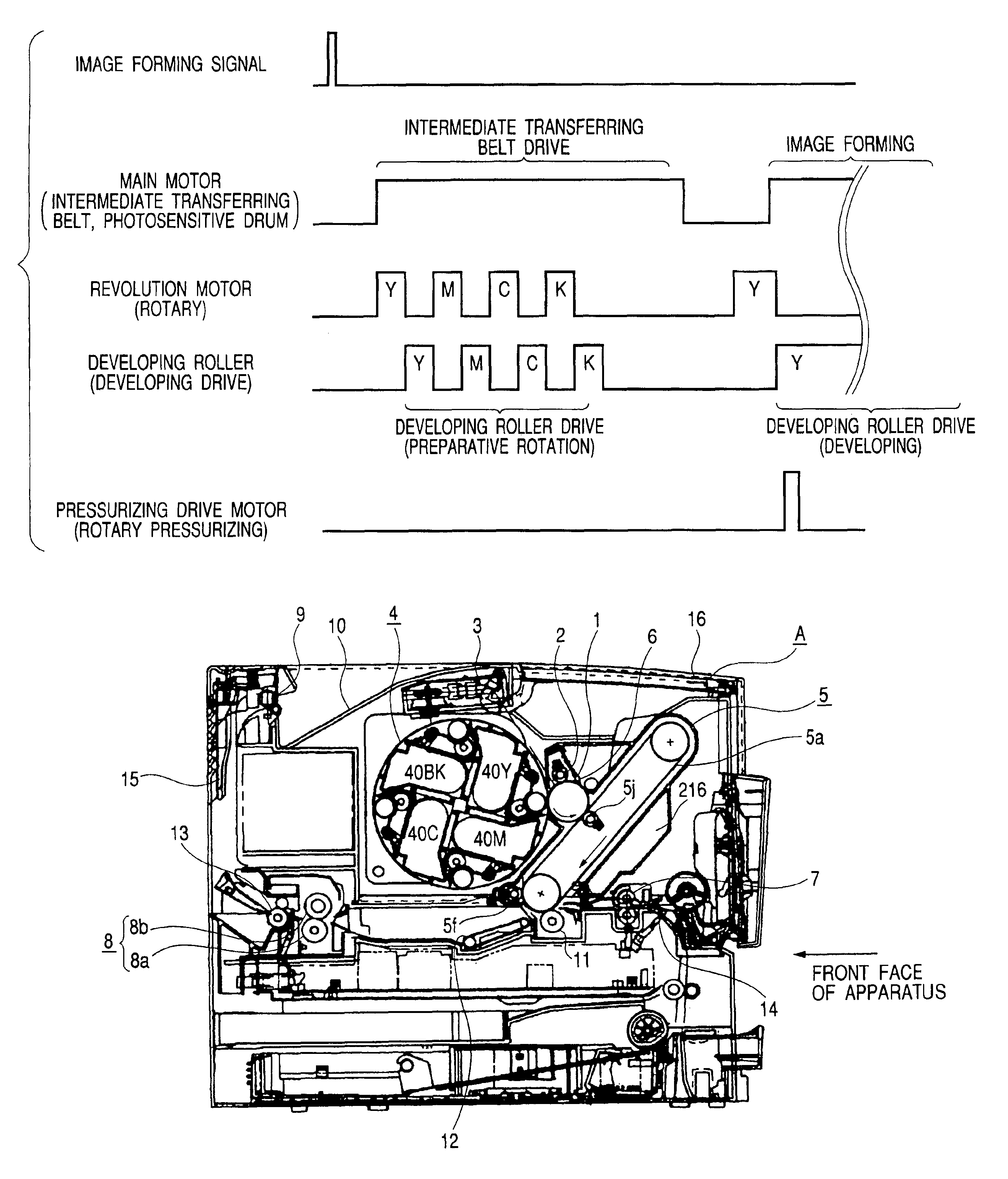
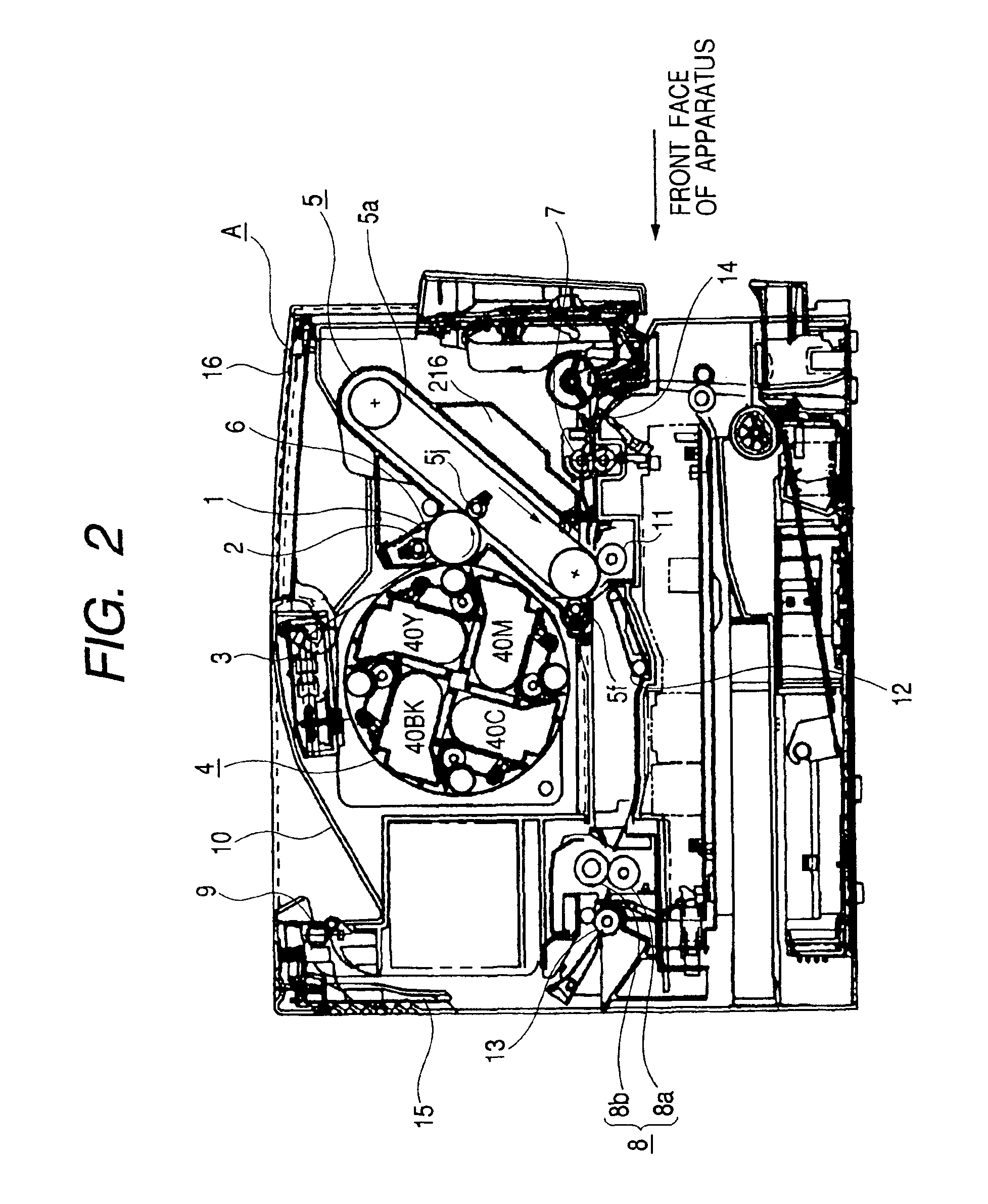
[0035]An image forming apparatus according to one embodiment of the present invention will now be described while referring to the accompanying drawings. In the following explanation, the front face of the apparatus is the face that is upstream in the direction in which a recording material is conveyed from a transferring process section to a fixing process section (right side in FIG. 2), and the left or the right of the main body of the image forming apparatus or a processing cartridge is the left or the right of the front face of the image forming apparatus. The longitudinal direction is the direction in parallel with the surface of the recording medium, and the direction that intersects (is almost orthogonal to) the direction in which the recording medium is conveyed.

(General Configuration of Image Forming Apparatus)

[0036]The general configuration of the image forming apparatus will now be described while referring to FIG. 2. FIG. 2 is a diagram showing the general configuration ...


PUM


Abstract

In order to suppress uneven densities in an image, an image forming apparatus includes an image bearing member; a first developing unit, including a first developer carrying member, for developing a first latent image formed on the image bearing member; a second developing unit, including a second developer carrying member, for developing a second latent image formed on the image bearing member after the first developing unit has developed the first latent image; and a rotary unit, for holding the first and the second developing units and for moving the first and the second developing unit to positions opposite said image bearing member. Upon the reception of an image forming signal at the image forming apparatus, the first and the second developer carrying members are rotated before the first latent image on the image bearing member is developed.

Description

BACKGROUND OF THE INVENTION[0001]1. Field of the Invention[0002]The present invention relates to an image forming apparatus, such as a copier or a printer, for forming an image on a recording medium using a recording technique, such as an electrophotographic recording method or an electrostatic recording method. In particular, the present invention relates to an image forming apparatus having a rotary unit for holding multiple developing devices.[0003]2. Description of the Related Art[0004]A developing device, which uses toner to develop an electrostatic latent image formed on a photosensitive member, is mounted in an image forming apparatus, such as an electrophotographic copier or printer. Generally, provided for the developing device are a developing roller and a blade for controlling the thickness of a toner layer.[0005]Especially when the image forming apparatus is one for which the developing roller is a flexible roller that is contacted by the blade, if the developing device ...

Claims


Application Information

Patent Timeline
Patent Type & Authority Patents(United States)
IPC IPC(8): G03G15/08G03G15/01G03G21/14
CPCG03G15/0178G03G15/0121G03G15/0173G03G2215/0177
Inventor TOBA, SHINJIROKANNO, KAZUHIKOSHAO, JUNSHIBATA, MASAHIRO
Owner CANON KK
Why Eureka
Try Eureka