Cause and effect logic application implementation

a logic and cause and effect technology, applied in the field of cause and effect logic application implementation, can solve the problems of interpretation errors, no recognized international standards apply to the definitions used in cause and effect logic,

Inactive Publication Date: 2005-09-06
GENERAL ELECTRIC CO
View PDF16 Cites 38 Cited by
  • Summary
  • Abstract
  • Description
  • Claims
  • Application Information

AI Technical Summary

Benefits of technology

[0004]In one embodiment, a method for Cause and Effect application logic implementation includes defining a formal methodology for specification of functional requirements for a target system based upon Cause and Effect notation and function blocks and employing a computer-aided specification tool-set to support capture and validation of functional requirements. The method further includes employing a software module to directly execute Cause and Effect application logic.
[0005]In another embodiment, a computer for Cause and Effect application logic implementation is configured to receive a defined formal methodology for specification of functional requirements for a target system based upon Cause and Effect notation and function blocks. The computer is further configured to capture at least one functional requirement, validate at least one captured functional requirement, and directly execute Cause and Effect application logic.
[0006]In yet another embodiment, a database includes data relating to Cause and Effect notation and data relating to at least one Function block.

Problems solved by technology

However, no recognized international standards apply to definitions used in cause and effect logic.
This inability to express more than simple combination coupled with the aforementioned lack of standards sometimes results in a safety system application logic definition which is ambiguous and hence subject to interpretation error.

Method used


Image

  • Cause and effect logic application implementation
  • Cause and effect logic application implementation
  • Cause and effect logic application implementation

Examples


Embodiment Construction

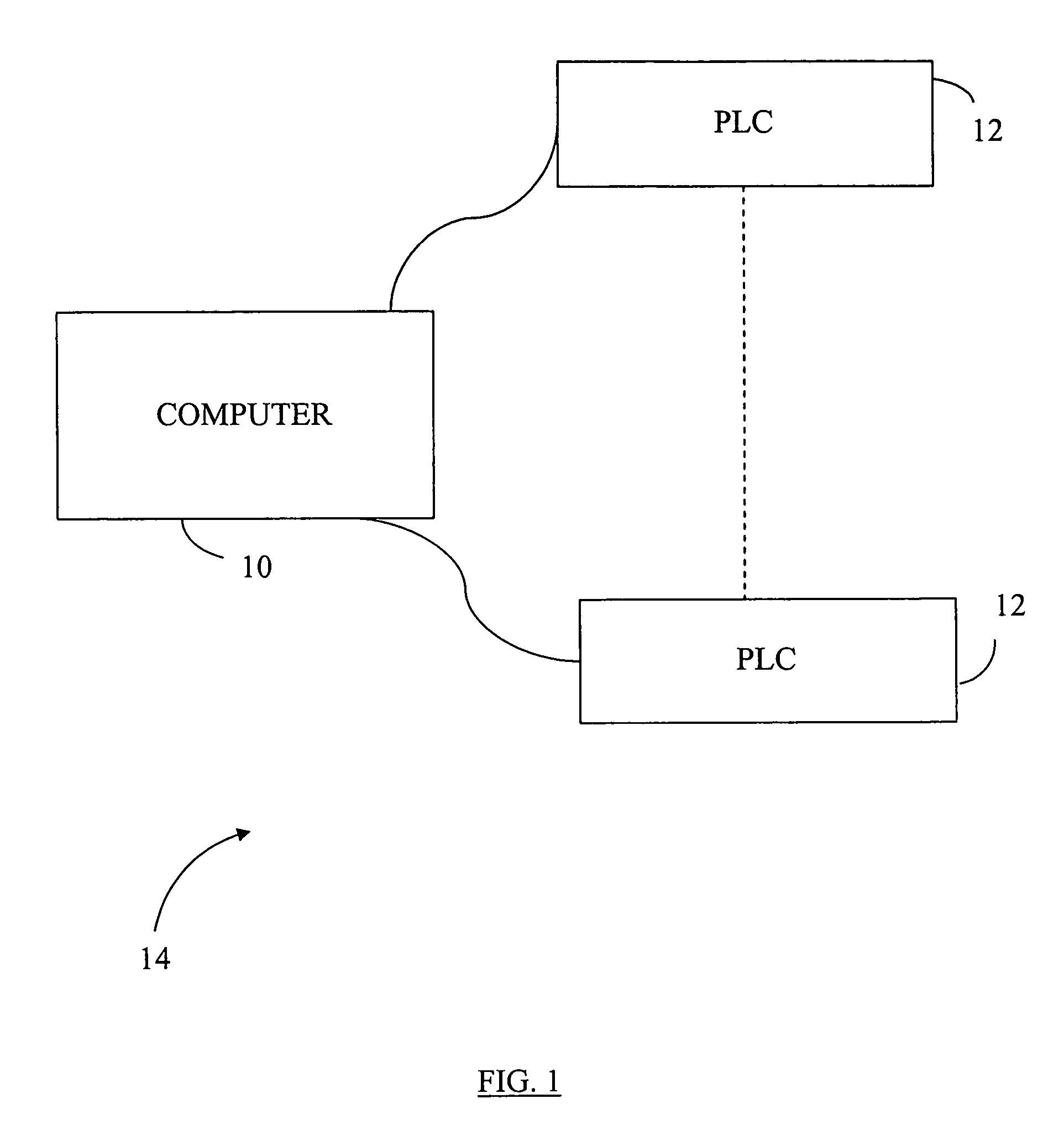
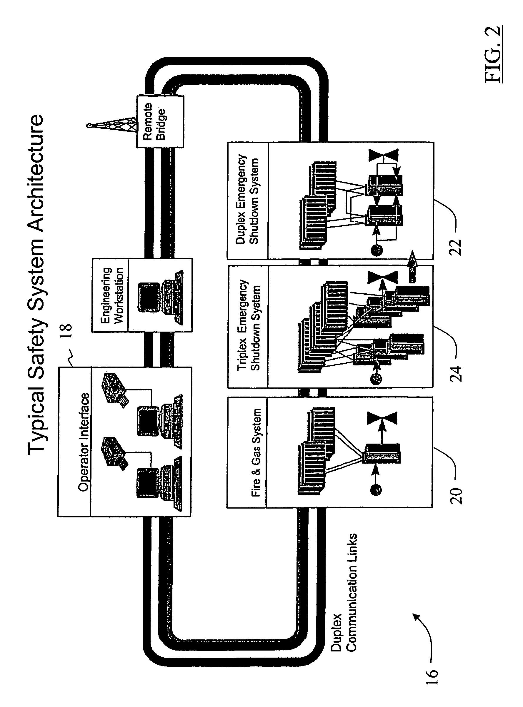
[0021]There is herein provided a formal methodology for implementation of cause and effect application logic in a safety-related application for a programmable logic controller (PLC) system. It is contemplated that the benefits of the present invention accrue to all implementations of cause and effect application logic including implementations in non-safety related applications for systems other than PLC systems. As shown in FIG. 1, the method utilizes at least one computer 10 in communication with at least one PLC 12 forming a system 14. As shown in FIG. 2, an exemplary safety system 16 includes an HMI (Human Machine Interface) 18, a Fire and Gas protection system 20, a duplex Emergency Shutdown System 22 and a triplex Emergency Shutdown System 24. As used herein, the term computer is not limited to just those integrated circuits referred to in the art as computers, but broadly refers to computers, processors, microcontrollers, microcomputers, application specific integrated circu...


PUM


Abstract

A method for Cause and Effect application logic implementation includes defining a formal methodology for specification of functional requirements for a target system based upon Cause and Effect notation and function blocks and employing a computer-aided specification tool-set to support capture and validation of functional requirements. The method further includes employing a software module to directly execute Cause and Effect application logic.

Description

CROSS REFERENCE TO RELATED APPLICATIONS[0001]This application claims the benefit of U.S. Provisional Application No. 60 / 201,001, filed May 1, 2000, which is hereby incorporated by reference in its entirety.BACKGROUND OF INVENTION[0002]This invention relates generally to cause and effect logic application implementation and, more specifically, to specifying functional requirements for cause and effect logic applications.[0003]Some safety related applications utilize cause and effect specifications. However, no recognized international standards apply to definitions used in cause and effect logic. Various industries, companies and individuals adopt their own standards. Additionally, each cause and effect definition includes a corresponding set of cause and effect notations that typically can only express relatively simple combination logic. This inability to express more than simple combination coupled with the aforementioned lack of standards sometimes results in a safety system appl...

Claims


Application Information

Patent Timeline
Patent Type & Authority Patents(United States)
IPC IPC(8): G06F9/00G06F9/455G05B19/05
CPCG05B19/056G05B2219/13107
Inventor QUINN, WILLIAM JOSEPH
Owner GENERAL ELECTRIC CO
Why Eureka
Try Eureka