Pivotable laser level

a laser level and pivoting technology, applied in the field of leveling instruments, can solve the problems of limiting the use of laser levels, no way that this could be accomplished by using laser levels alone, and not precisely parallel

Inactive Publication Date: 2005-09-13
AWI ACQUISTION CO
View PDF14 Cites 44 Cited by
  • Summary
  • Abstract
  • Description
  • Claims
  • Application Information

AI Technical Summary

Benefits of technology

[0016]A further embodiment of the present invention is where the hinge plate assembly is modified by the adjusting plate including an enlarged recess. The base is to closely confo

Problems solved by technology

This type of usage greatly limits the use of a laser level.
For example, if a homeowner or tradesman desires to project a line spaced from a wall/floor joint but yet parallel to that joint, there was no way that this could be accomplished by use of

Method used


Image

  • Pivotable laser level
  • Pivotable laser level
  • Pivotable laser level

Examples


Embodiment Construction

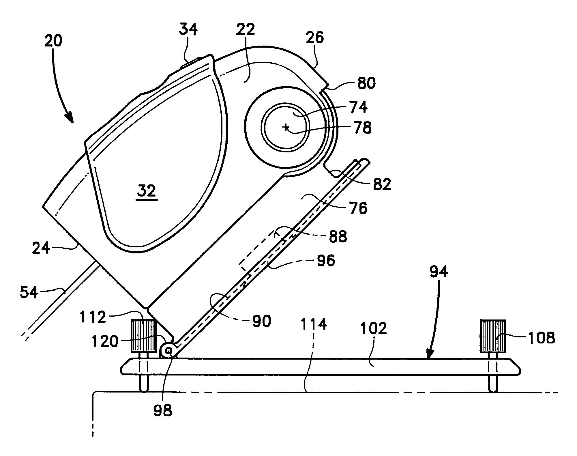
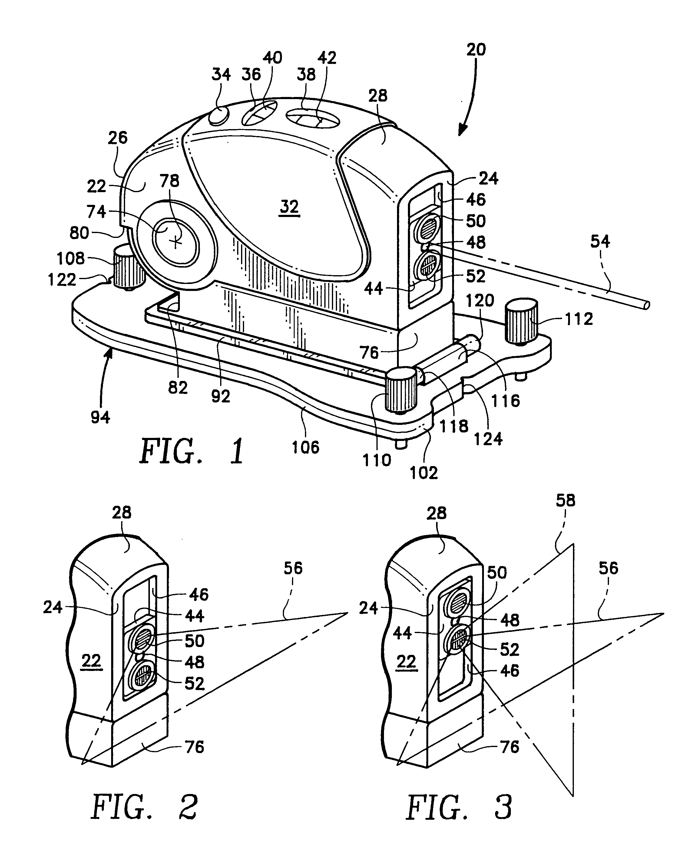
[0049]Referring particularly to FIG. 1 of the drawings, there is shown the pivotable laser level 20 of this invention which has a housing 22. Housing 22 has a front end which is formed into an end face 24. The housing 22 has a rear edge 26. In between the end face 24 and the rear edge 26 is a top edge28. Also located between the end face 24 and the rear edge 26 is a bottom edge 30. Generally, the housing 22 will be constructed of a metallic material, such as aluminum. However, it is considered to be within the scope of this invention that other rigid materials could be used, such as plastic.

[0050]Mounted in conjunction with the housing 22 is a hand grip 32. Generally, the hand grip will be constructed of a resilient type of material, such as rubber or plastic. The hand grip 32 extends down both sides of the housing 22 and is also located across the top edge 28. It is the function of the hand grip 32 to provide a comfortable gripping surface which is to be grabbed by a human user and...


PUM


Abstract

A laser level that is mounted within a housing with the housing being pivotally movable relative to a base. The base is then to be placeable in conjunction with a hinge plate assembly composed of a main plate and an adjusting plate with the adjustable plate being also pivotally movable relative to the main plate. The result is the housing is pivotable in a clockwise direction within a first range of motion and then is pivotable in a counterclockwise direction within a second range of motion. The laser level of this invention is to project a laser beam onto a wall with the laser beam being in the form of a horizontal line or a vertical line and horizontal line. The vertical line is to be aligned with a particular mark on a wall. The horizontal line can be aligned with a wall/floor joint so that the horizontal line will be parallel to this joint when the horizontal line is moved away from the wall/floor joint and projected at a selected height on the wall.

Description

BACKGROUND OF THE INVENTION[0001]1. Field of the Invention[0002]The present invention relates generally to a leveling instrument and more particularly to a leveling instrument which uses a beam of light, specifically a laser beam, to project a single horizontal reference line, both a horizontal reference line and a vertical reference line or a reference dot.[0003]2. Description of the Related Art[0004]Laser levels have been used in the field of construction for many years. The typical procedure in conjunction with a laser level is to project either a precisely horizontal line or to project a line from one mark on a wall to another mark on a wall. The common form of laser level requires that the laser level unit be mounted directly on the wall surface on which the line is to be projected. This type of usage greatly limits the use of a laser level. For example, if a homeowner or tradesman desires to project a line spaced from a wall / floor joint but yet parallel to that joint, there wa...

Claims


Application Information

Patent Timeline
IPC IPC(8): G01C9/00G01C9/06G01C15/02
CPCG01C15/008Y10S33/21
Inventor BUDROW, WILLIAM B.MUNSHI, STEPHEN B.HOLDRIDGE, GREG L.
Owner AWI ACQUISTION CO
Why Eureka
Try Eureka