Steerage locking system for vehicle

Inactive Publication Date: 2005-09-13
HONDA LOCK MFG CO LTD
View PDF26 Cites 30 Cited by
  • Summary
  • Abstract
  • Description
  • Claims
  • Application Information

AI Technical Summary

Benefits of technology

[0015]With such arrangement of the sixth feature, the knob cap closing the keyhole is fitted into the opening which is provided in the control knob and leads to the keyhole in the rotor. Therefore, when the mechanical key is not used, the keyhole becomes invisible by closing the keyhole by the knob cap, leading to an improvement in appearance. Moreover, the knob cap is fitted into the opening in such a

Problems solved by technology

In the conventional system, however, a control knob is integrally formed on a rotor, and when the maintenance of the control knob or a part disposed behind the control

Method used


Image

  • Steerage locking system for vehicle
  • Steerage locking system for vehicle
  • Steerage locking system for vehicle

Examples


Embodiment Construction

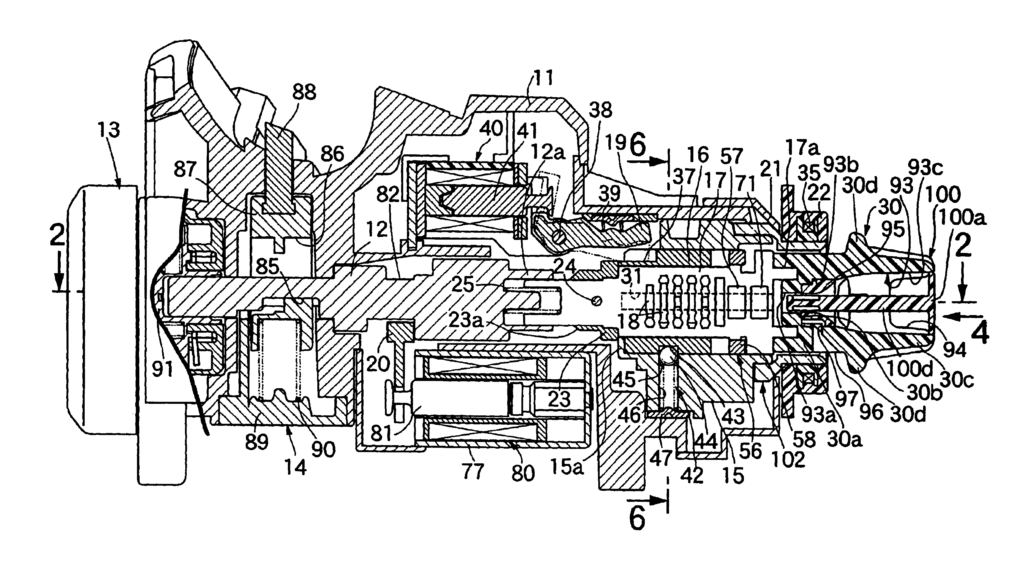
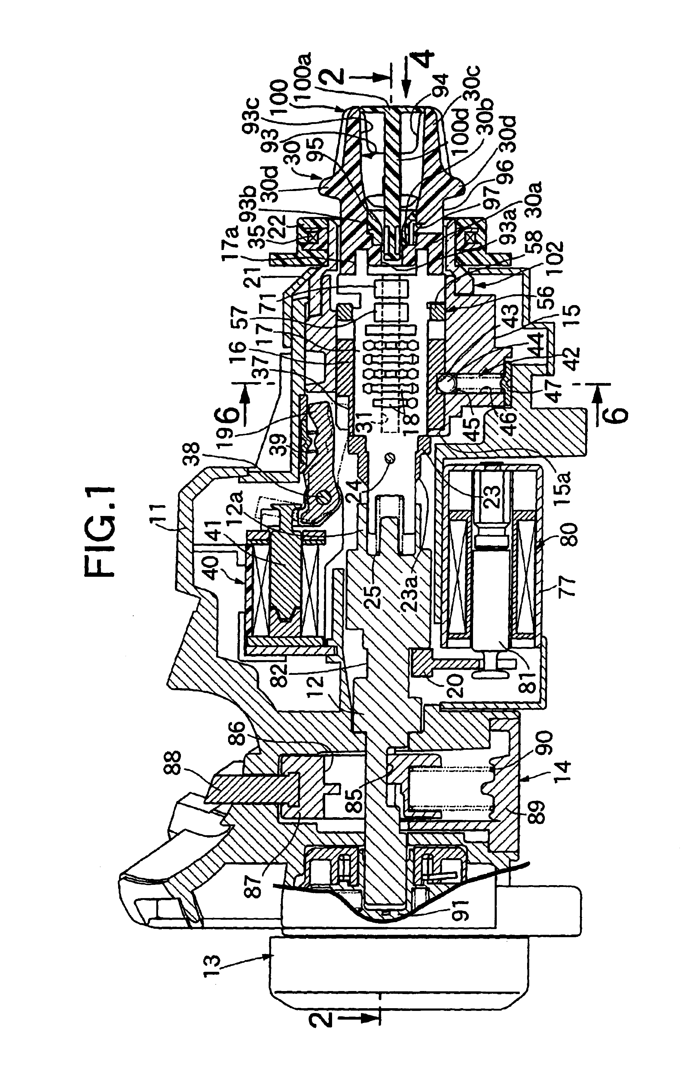
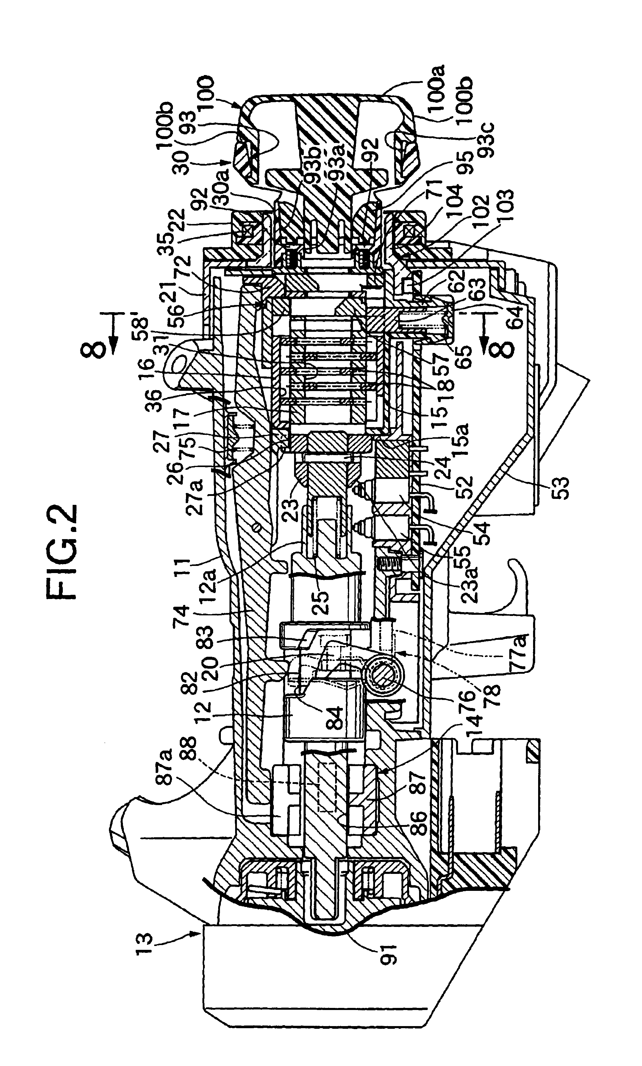
[0027]The present invention will now be described by way of a preferred embodiment with reference to FIGS. 1 to 10. Referring first to FIGS. 1 and 2, a steerage locking system includes a body 11 made of a metal and mounted to a steering column (not shown), a cooperative turn shaft 12 turnably supported in the body 11, a rotary switch 13 mounted to a rear end of the body 11 and connected a rear end (a left end in FIGS. 1 and 2) of the cooperative turn shaft 12, a locking mechanism 14 capable of being switched over between a locking state inhibiting the turning of a steering shaft (not shown) and a unlocking state permitting the turning of the steering shaft in response to the turning of the cooperative turn shaft 12, a housing 15 disposed in a front portion of the body 11 in front of the cooperative turn shaft 12 to be fixed thereto, a cylinder 16 turnably supported in the housing 15, a rotor 17 which is disposed coaxially with the cooperative turn shaft 12 and relatively turnably in...


PUM


Abstract

In a steerage locking system for a vehicle, including a control knob mounted to a rotor capable of being turned from a LOCK position via an ACC position and an ON position to a START position, the control knob is detachably fastened to a front end of the rotor by a screw member from axially outside the rotor. Thus, the maintenance such as exchange of the control knob is facilitated.

Description

BACKGROUND OF THE INVENTION[0001]1. Field of the Invention[0002]The present invention relates to a steerage locking system for a vehicle, and particularly to an improvement in a steerage locking system for a vehicle, comprising a control knob mounted to a rotor capable of being turned from a LOCK position via an ACC position and an ON position to a START position.[0003]2. Description of the Related Art[0004]A conventional system is already known, for example, from Japanese Patent Publication No.6-74683 and the like.[0005]In the conventional system, however, a control knob is integrally formed on a rotor, and when the maintenance of the control knob or a part disposed behind the control knob is carried out, it is disadvantageously necessary to remove the control knob along with the rotor. There is also a steerage locking system in which a control knob is mounted to a rotor by press-fitting or by claw-engagement. In both cases, however, the control knob cannot be removed easily.SUMMAR...

Claims


Application Information

Patent Timeline
IPC IPC(8): B60R25/02B60R25/04
CPCB60R25/02126B60R25/04Y10T70/8649Y10T70/5664Y10T70/5898Y10T70/5956Y10T70/5889
Inventor SHIGEYAMA, KATSUYOSHITANIGUCHI, TAKESHISASAKI, MITSUOYOSHIMURA, KENTARONAKAI, TOMOAKITAKIZAWA, KENICHISUZUKI, MASASHI
Owner HONDA LOCK MFG CO LTD
Why Eureka
Try Eureka