

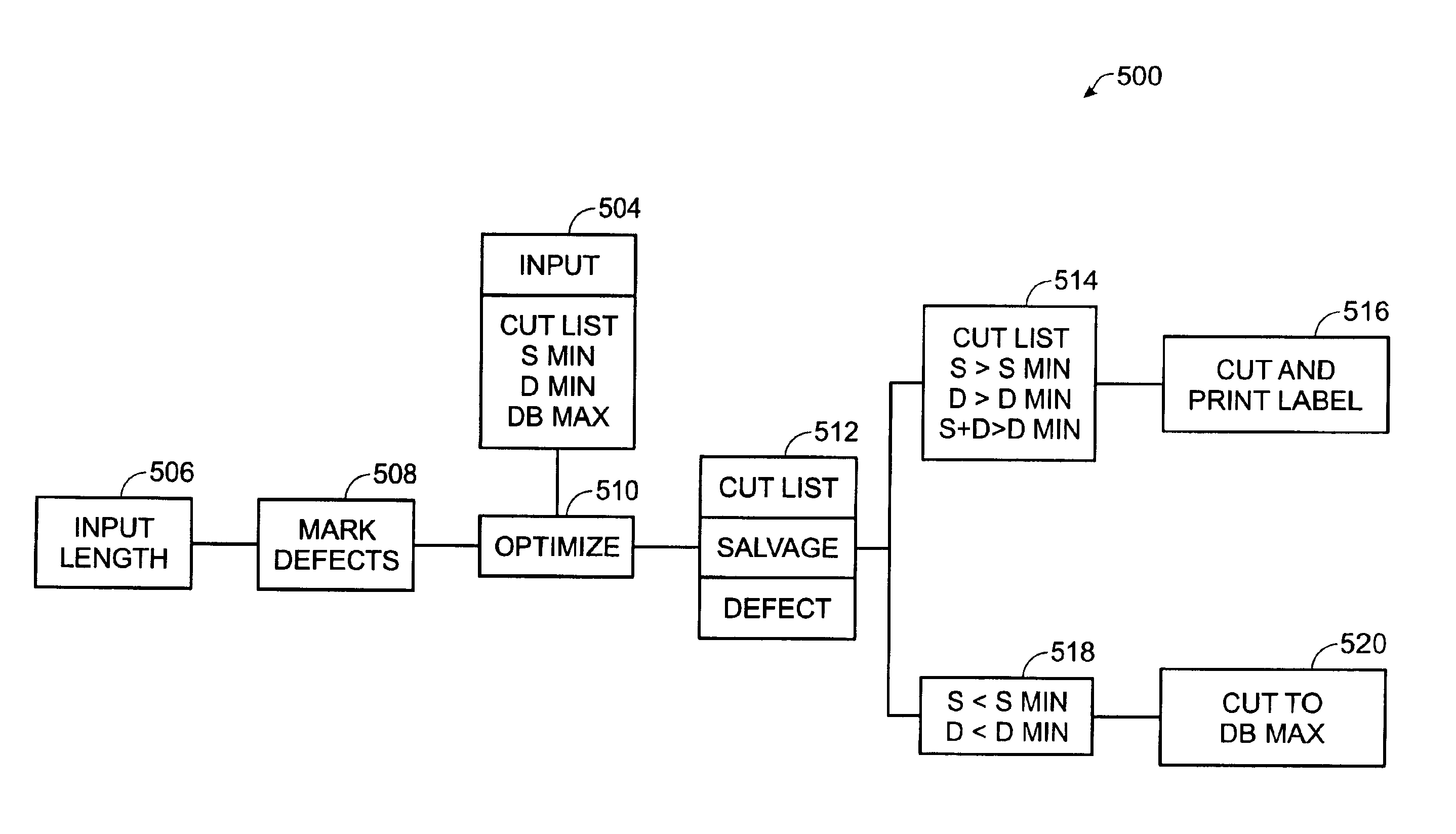
Method to control optimized cutting of stock to satisfy a cut list
a technology of optimized cutting and stock, applied in the field of waste management and system processing of materials, can solve the problems of waste of cutting remaining pieces that do not conform to the cut list, and achieve the effect of saving resources and reducing was
- Summary
- Abstract
- Description
- Claims
- Application Information
AI Technical Summary
Benefits of technology
Problems solved by technology
Method used
Image

Examples
Embodiment Construction
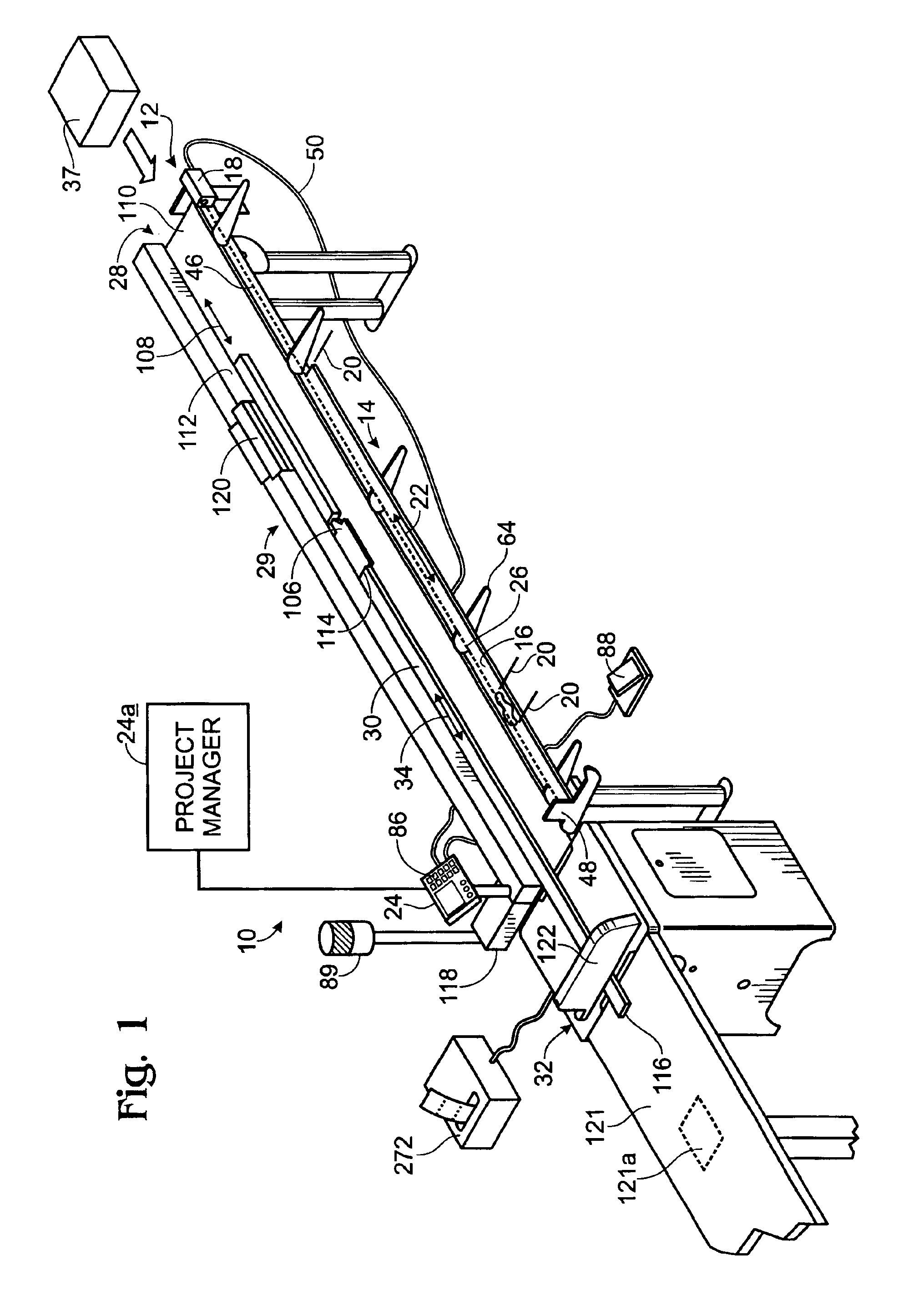
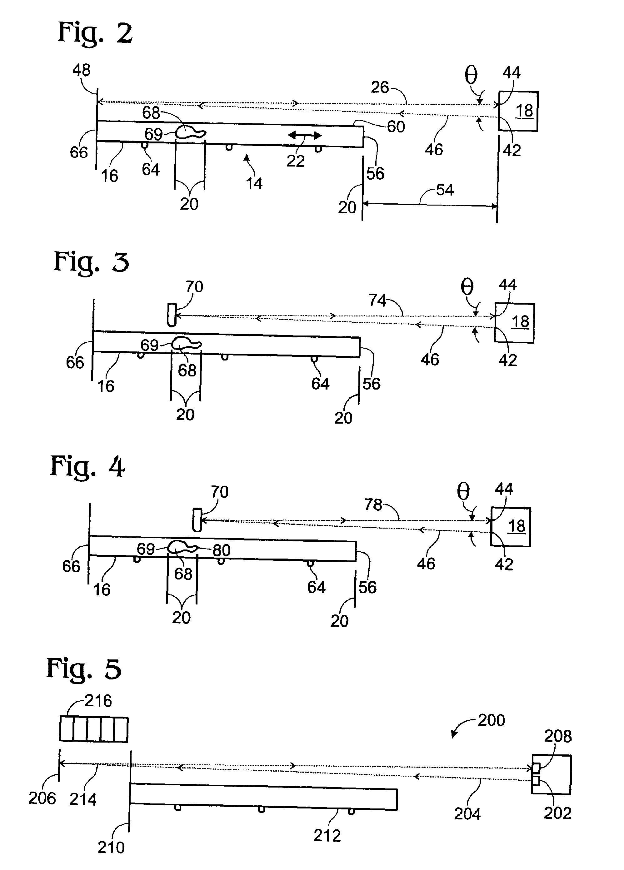
[0015]An example of an automated processing system constructed in accordance with the present invention is shown generally at 10 in FIG. 1. System 10 includes a marking assembly 12 positioned along a front portion of the system. Marking assembly 12 includes a marking station 14 to orient an article or material 16 relative to an optical measuring device 18. The article may be a wood product, metal, plastic, ceramic, and / or the like. The article may have any suitable shape and size, and may be elongate to define a long axis, which also may be a processing axis.
[0016]Feature locations 20 along a processing axis 22 of material 16 may be input by a user to the optical measuring device 18, which communicates the feature locations to a controller 24. Another computer 24a may be used remotely from controller 24 to store, edit, combine, or modify cut lists prior to downloading one or more cut lists to controller 24. Marking assembly 12 allows a user to virtually mark feature locations 20 of ...
PUM
| Property | Measurement | Unit |
|---|---|---|
| Length | aaaaa | aaaaa |
| Defects | aaaaa | aaaaa |
Abstract
Description
Claims
Application Information