Structure for mounting a net member to a frame for a seat or backrest of a chair

a technology for mounting structures and net members, which is applied in the field of structure for mounting net members to seat frames, can solve the problems of difficult to obtain frictional force enough to hold a sitting person, difficult to mount the outer periphery of the net member to the seat frame at non-uniform tensile force, and high labor intensity, and achieves low tensile force and low cost. , the effect of suitable comfort and appearan

Inactive Publication Date: 2005-09-13
OKAMURA CORP
View PDF27 Cites 183 Cited by
  • Summary
  • Abstract
  • Description
  • Claims
  • Application Information

AI Technical Summary

Benefits of technology

[0006]In view of the disadvantages, it is a principal object of the present invention to provide the structure for stretching a net member to a frame of a seat or backrest of a chair by a relatively simple low uniform tensile force.
[0007]It is another object of the present invention to provide a method of stretching a net member over a frame of a seat or backrest of a chair uniformly and simply.
[0008]It is a further object of the present invention to provide a mesh-stretched chair having suitable comfort and appearance without slippage of fibers to provide frictional enough force to hold a sitting person.

Problems solved by technology

However, it is not an easy procedure to mount the outer periphery of the net member to the seat frame at non-uniform tensile force.
It requires much labor, and owing to non-uniform tensile force.
Excessive tensile force is applied to the net member around a bonding bolt which causes cracking.
The mesh pattern which appears on the surface is not only monotypic but also likely to slip, so that it is difficult to obtain frictional force enough to hold a sitting person.
Tensile strength is not suitably applied to the seat in a depth direction and the backrest in a vertical direction.
So the seat and backrest do not provide enough elasticity.

Method used


Image

  • Structure for mounting a net member to a frame for a seat or backrest of a chair
  • Structure for mounting a net member to a frame for a seat or backrest of a chair
  • Structure for mounting a net member to a frame for a seat or backrest of a chair

Examples


first embodiment

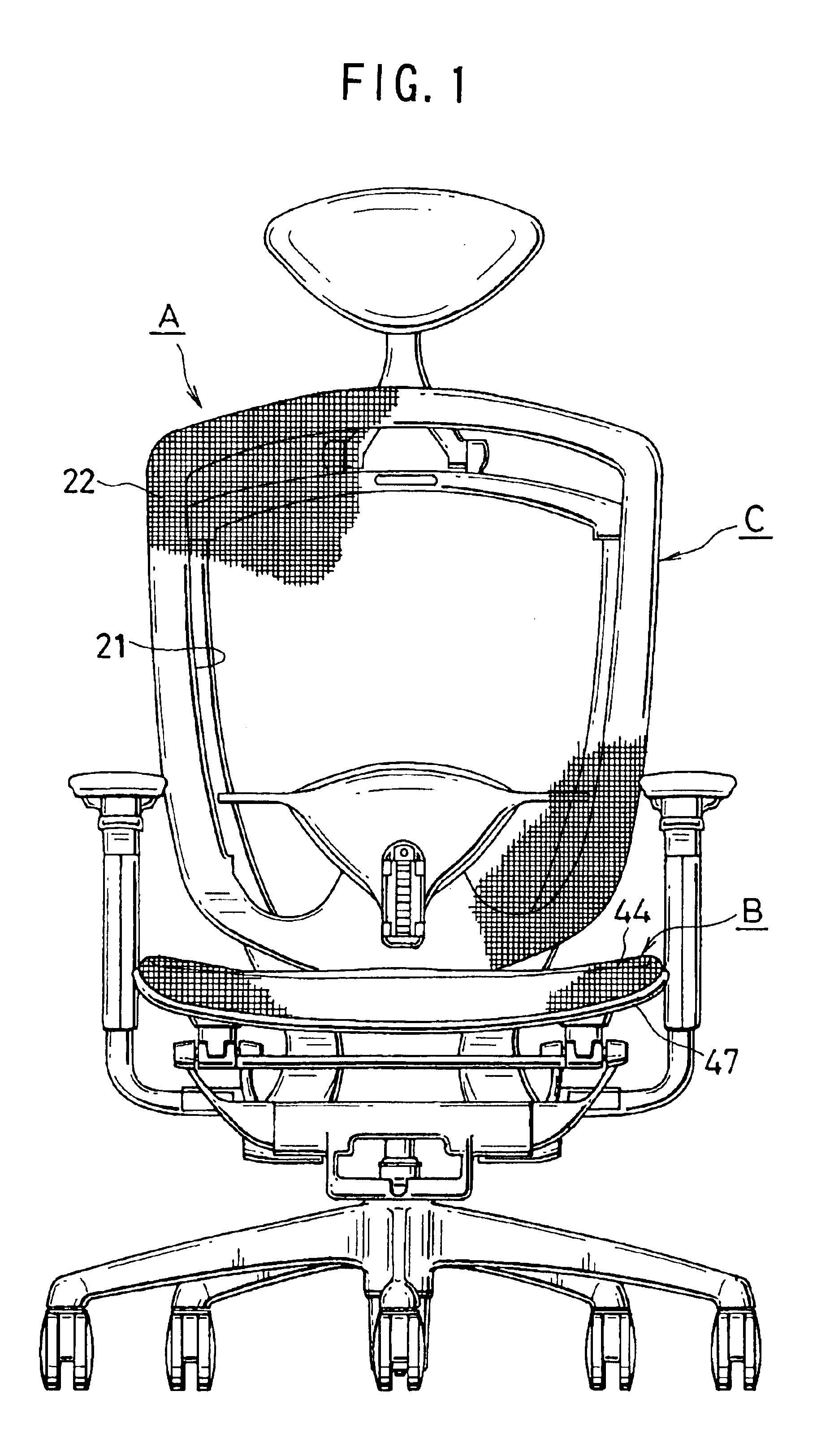
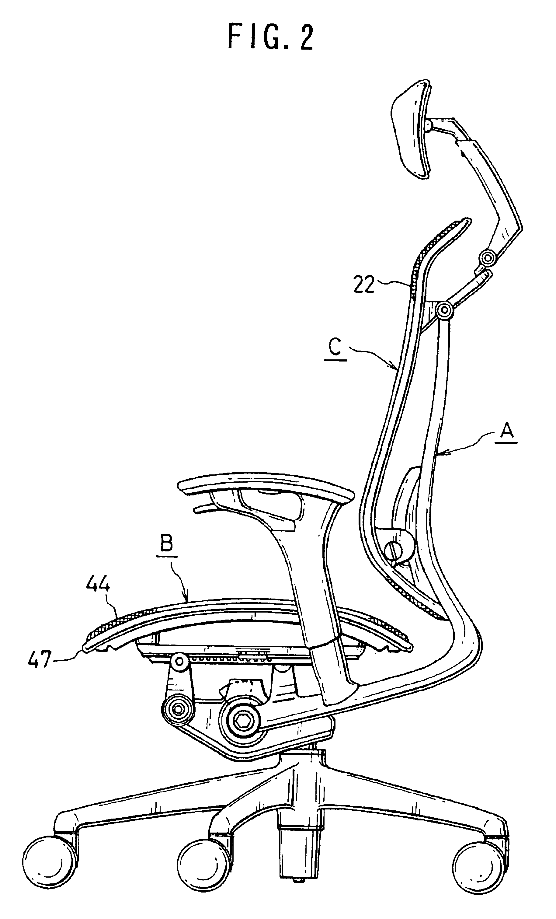
[0034]the present invention will be described. The present invention is applied not only to a seat “B” of a chair “A” in FIG. 2 but also to the backrest “C” of the chair “A”.

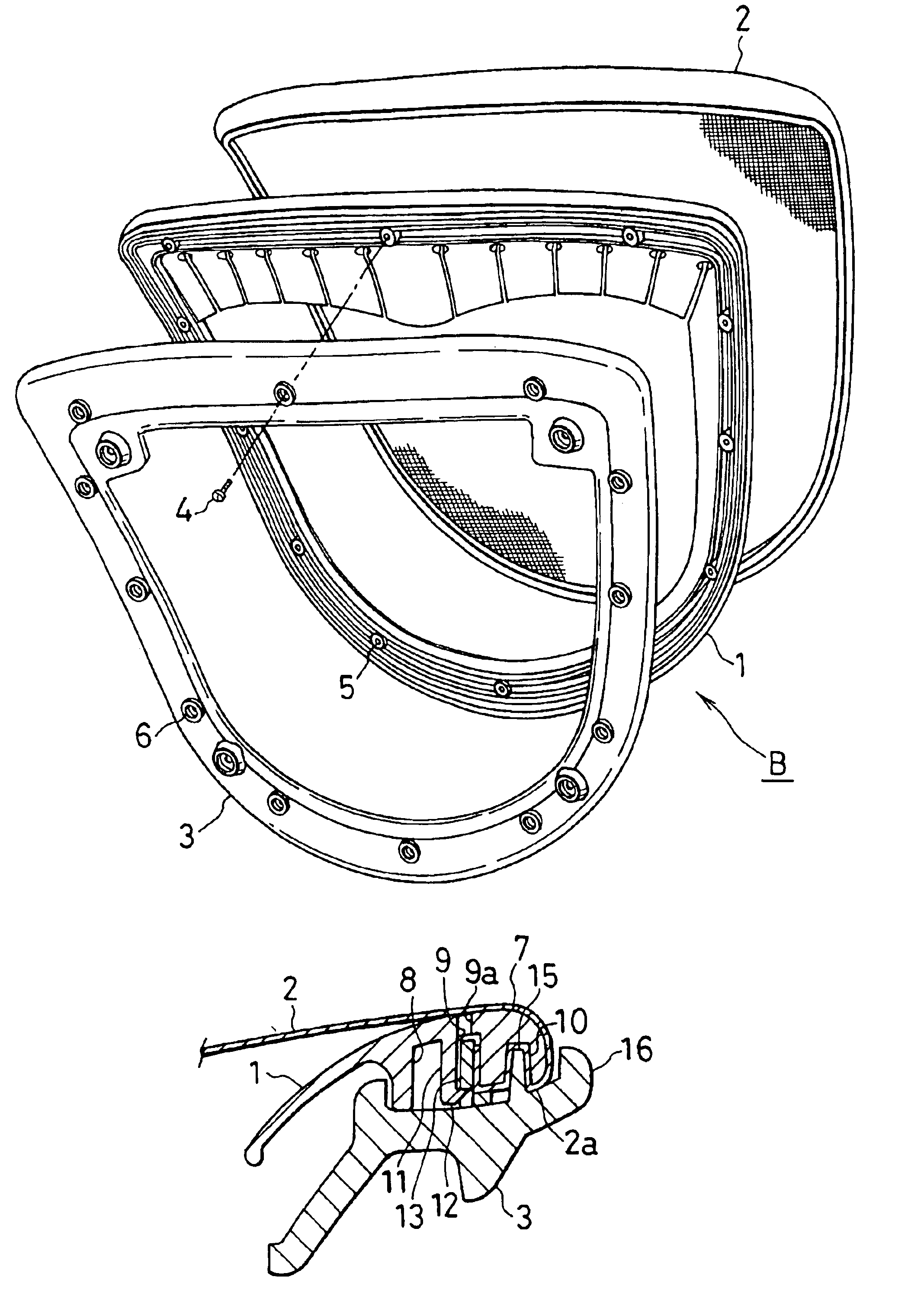
[0035]As shown in FIGS. 4 and 5, in the seat “B”, the periphery of a net member 2 such as high tension plastic is put on the outer periphery of a closed-loop seat frame 1, and folded. A binding frame 3 similar to the seat frame 1 in shape is put on the lower surface of a folded portion 2a and bound by bolts 4.

[0036]There are formed a plurality of threaded bores 5 and through-bores 6 which are corresponding to each other in position in the lower surface of the seat frame 1 and the binding frame 3 respectively.

[0037]As shown in FIG. 6, the folded portion 2a of the net member 2 is held between the seat frame 1 and the binding frame 3 as below. The outer periphery 7 of the seat frame 1 comprises a hard thickened portion, and the lower surface of the periphery 7 has an annular clearance groove 8, an annular engagemen...

second embodiment

[0051]FIGS. 15 to 18 illustrate the present invention in which a peripheral groove 17 is formed on the upper outer circumferential surface of the seat frame 1. An edge member 18 is engaged on the peripheral groove 17 to apply outward force to a net member 2. The peripheral groove 17 and the edge member 18 may be preferably provided on the whole circumference of the seat frame 1. The edge member 18 may be made of flexible synthetic resin wire such as soft polyurethane having a diameter of 3 to 10 mm.

[0052]FIG. 16 is a perspective view of FIG. 15, and FIG. 17 is a vertical sectional view of a portion having a bolt and the edge member 18.

[0053]Owing to the edge member 18 in the peripheral groove 17, stronger tensile force is applied to the net member 2 uniformly.

third embodiment

[0054]the present invention is shown in FIG. 18, in which a protrusion 19 is formed at the upper end of a peripheral groove 17. An edge member 18 and a net member 2 are firmly held between the protrusion 19 and a protection flange 16 of a binding frame 3 thereby preventing escape of the edge member 18 and elongation of the net member 2.

[0055]A mesh-stretched chair is schematically shown in FIG. 19, in which a mesh 44 for the seat “B” comprises a woven or knitted structure of a series of warps 24 and a series of wefts 29 crossed thereto. The series of warps 24 comprise a number of high tension warps 23; and the series of wefts 29 comprises a series of elastic yarns 26 of a number of elastic yarns 25 and a series of chenille yarns 28 of a number of chenille yarns 27.

[0056]In the example, the series of elastic yarns 26 comprise four elastic yarns 25, and the series of chenille yarns 28 comprise two chenille yarns 27. The warp 23 may be preferably made of polyester multufilament having ...


PUM


Abstract

A net member is stretched over a frame for a seat and backrest of a chair. An engagement member attached to the end of the net member is inserted into an engagement groove on the lower surface of the basic frame. A binding frame is pressed onto the lower surface of the basic frame and the net member is fixed between the basic frame and the binding frame by the engagement piece.
Warps are woven or knitted in a mesh structure over the seat and backrest to wefts comprising elastic yarns and chenille yarns.

Description

BACKGROUND OF THE INVENTION[0001]The present invention relates to the structure for mounting a net member to a frame for a seat and the backrest of a chair, a method of mounting the net member to the frame and a chair with a mesh in which warps are woven or knitted with wefts.[0002]In a conventional seat structure of a chair in which a high tension elastic net member including a porous plate is stretched over a closed-loop seat frame, the outer periphery of the net member is put over the upper outer side surface of the seat frame and folded into the lower surface of the seat frame. The folded portion is fixed to the seat frame by a screw. Japanese Patent Publications No.11-244103 and 2002-165672 disclose the structure.[0003]However, it is not an easy procedure to mount the outer periphery of the net member to the seat frame at non-uniform tensile force. It requires much labor, and owing to non-uniform tensile force. Wrinkles and slacks occur in connected portions of the net member. ...

Claims


Application Information

Patent Timeline
Patent Type & Authority Patents(United States)
IPC IPC(8): A47C7/22A47C7/28A47C23/00A47C31/02A47C23/26A47C7/02A47C31/00
CPCA47C7/282A47C7/40A47C31/023A47C31/04A47C7/02A47C31/02
Inventor NUMA, NAOKINARITA, TETSUYAIGARASHI, RYO
Owner OKAMURA CORP
Why Eureka
Try Eureka