
Braking force control apparatus

a technology of braking force and control apparatus, which is applied in the direction of gear ratio and output torque becoming temporarily unstable, shifting shock, vibration to the vehicle, etc., to achieve the effect of suitable riding comfor

Active Publication Date: 2022-08-23
TOYOTA JIDOSHA KK
View PDF10 Cites 0 Cited by
  • Summary
  • Abstract
  • Description
  • Claims
  • Application Information

AI Technical Summary

Benefits of technology

[0005]During the coasting, a torque from the wheel side caused by the inertial force of the vehicle is distributed and input to the generator and the transmission. When the state of the regenerative power generation by the generator is transited from the execution state to the stop state, the absolute value of the input torque to the generator is decreased due to decrease in regenerative load, and thus the absolute value of the input torque to the transmission is accordingly increased. Since the control on the gear shift of the transmission and the control on the regenerative power generation are executed independently of each other, the regenerative power generation may stop during the downshift transition period in the coasting state, and thus the comfortable riding feeling may be deteriorated due to a shift shock.
[0006]The present disclosure has been made in light of the above problems, and an object of the present disclosure is to provide a braking force control apparatus that can realize a suitable riding comfort in a coasting state of a vehicle.
[0008]The present disclosure can provide a braking force control apparatus capable of realizing a suitable riding comfort in a coasting state of a vehicle.

Problems solved by technology

There is a certain transition period in the downshift operation in the transmission, and if an input torque to the transmission varies during this transition period, the gear ratio and the output torque become temporarily unstable because of the internal structure of the transmission, which may cause a shift shock such as sudden vibrations to the vehicle.
Since the control on the gear shift of the transmission and the control on the regenerative power generation are executed independently of each other, the regenerative power generation may stop during the downshift transition period in the coasting state, and thus the comfortable riding feeling may be deteriorated due to a shift shock.

Method used


Image

  • Braking force control apparatus
  • Braking force control apparatus
  • Braking force control apparatus

Examples


first embodiment

[0017]Hereinafter, the first embodiment will be described in detail with reference to the drawings. Note that a speed, an acceleration, and the like are represented by values with reference numerals while the vehicle traveling direction is set in a positive direction.

Configuration

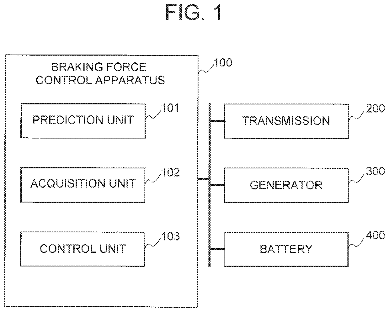
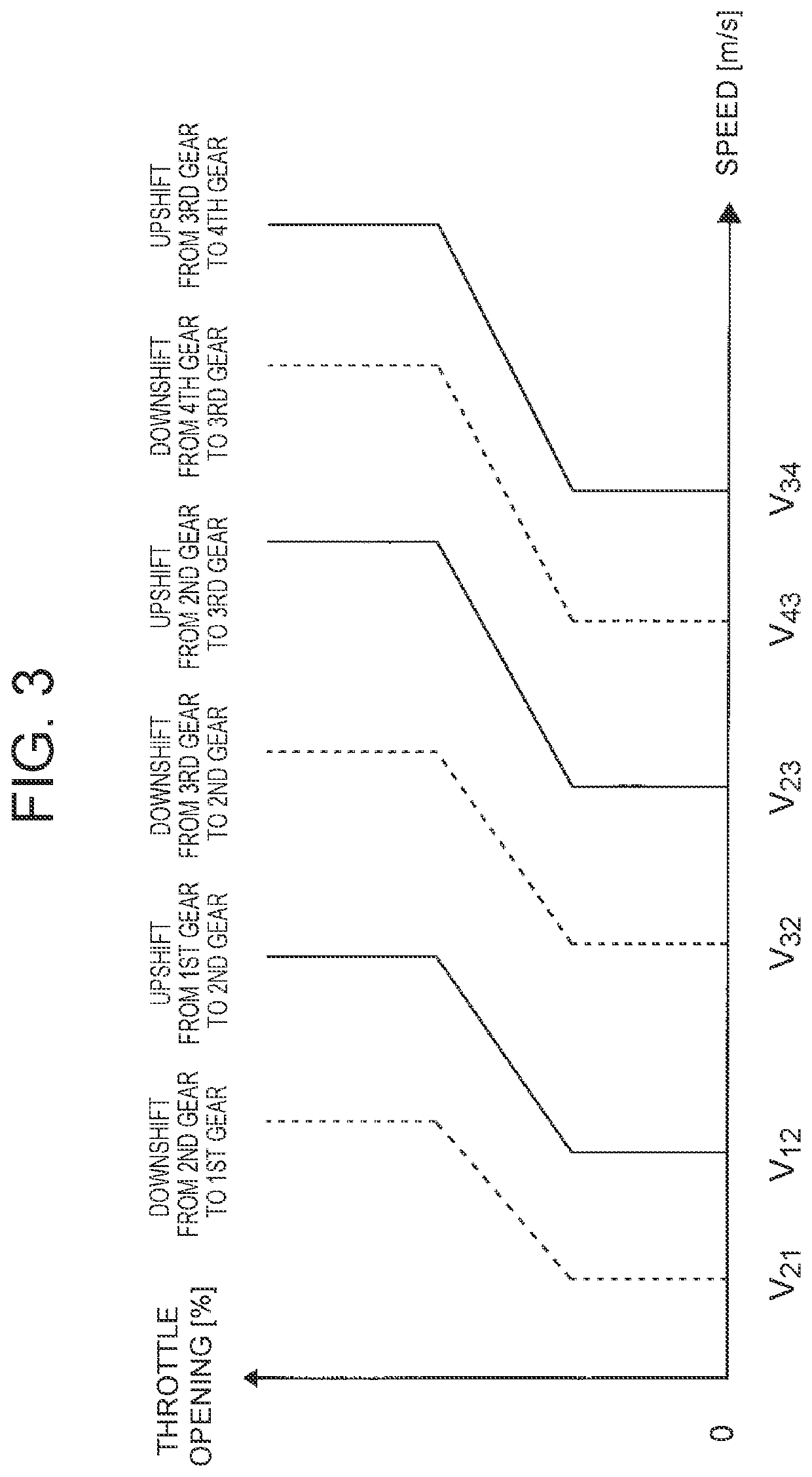
[0018]FIG. 1 shows a configuration of a braking force control apparatus 100 and surroundings thereof mounted in a vehicle according to the present embodiment. The vehicle includes the braking force control apparatus 100, a transmission 200 that is a stepped automatic transmission, a generator 300 that can perform regenerative power generation such as an alternator and a motor, and a battery 400 that charges electric power from the regenerative power generation by the generator 300. The transmission 200 and the generator 300 can generate a braking force while the vehicle is in a coasting state. The braking force can be generated by an apparatus such as an engine (not shown) other than the transmission 200 an...

second embodiment

[0039]Hereinafter, the second embodiment will be described with reference to the drawings. Descriptions of the same matters as those in the first embodiment will be omitted or simplified. The configuration of each component of the braking force control apparatus 100 according to the present embodiment is the same as that of the first embodiment. In the present embodiment, the control unit 103 specifically predicts time t2 from a current time until the regenerative power generation of the generator 300 is stopped.

Process

[0040]FIG. 6 is a flowchart showing an example of control of the regenerative power generation performed by the braking force control apparatus 100 while the user is driving the vehicle. This process is executed in a state in which the regenerative power generation by the generator 300 is possible while the vehicle is powered on and can travel.

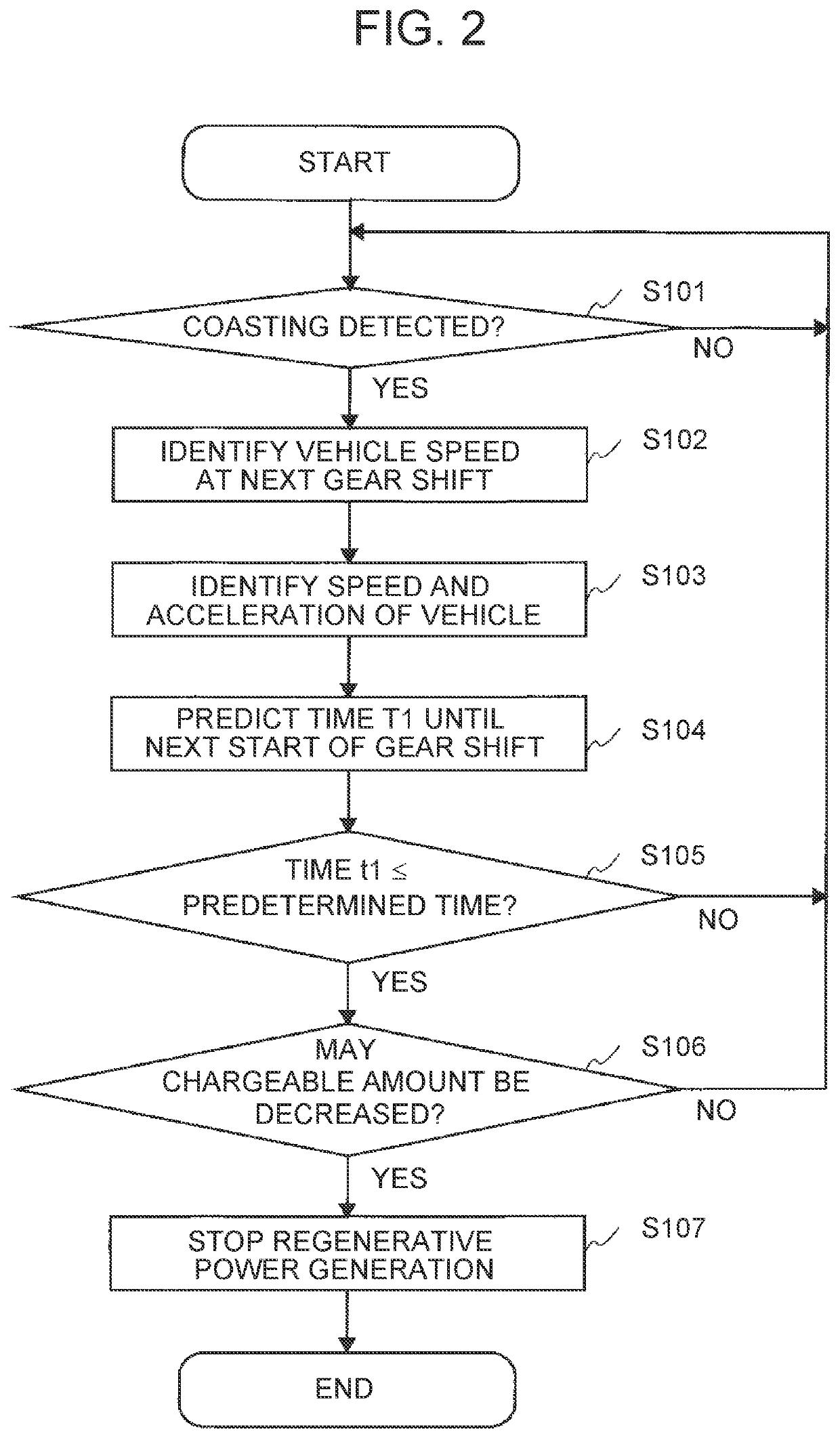
[0041](Step S201 to S204): The process in each step is the same as that in steps S101 to S104 in the first embodiment. As in t...


PUM


Abstract

A braking force control apparatus includes: a prediction unit that predicts a time from a present time until a next start of the gear shift operation in the stepped automatic transmission based on a speed of the vehicle; an acquisition unit that acquires a state of a battery charged by a regenerative power generation of the regenerative generator; and a control unit that stops the regenerative power generation by the regenerative generator before the gear shift of the stepped automatic transmission is started, when it is determined, during the regenerative power generation by the regenerative generator, that the regenerative power generation by the regenerative power generator may be stopped due to the state of the battery during the gear shift operation of the stepped automatic transmission, based on a prediction result by the prediction unit and the state of the battery acquired by the acquisition unit.

Description

INCORPORATION BY REFERENCE[0001]The disclosure of Japanese Patent Application No. 2019-086025 filed on Apr. 26, 2019 including the specification, drawings and abstract is incorporated herein by reference in its entirety.BACKGROUND1. Technical Field[0002]The present disclosure relates to a braking force control apparatus that is mounted in a vehicle and controls the braking force of the vehicle.2. Description of Related Art[0003]In vehicles, various technologies have been proposed in order to improve comfortable riding feeling and operational feeling. For example, Japanese Patent Application Publication No. 10-280990 discloses a fuel cut control apparatus that supplements a deceleration force by an alternator, an air conditioner, a brake, a gear shift, etc., in order to obtain an expected deceleration force when fuel cut is prohibited to prevent catalyst deterioration at a high catalyst temperature, during vehicle deceleration. Japanese Patent Application Publication No. 2006-297994 ...

Claims


Application Information

Patent Timeline
Patent Type & Authority Patents(United States)
IPC IPC(8): B60W10/18B60W10/08
CPCB60W10/18B60W10/08B60W2510/1005B60W2510/244B60W2520/105
Inventor MATSUMIYA, YUKISATO, SHUNFUJIWARA, HIROYANISHIU, MASAHIRO
Owner TOYOTA JIDOSHA KK
Learn More