
Reduction gear unit

a gear unit and gear technology, applied in the direction of gearing details, gearing, transportation and packaging, etc., can solve the problems of reducing the overall dimensions of the electric power steering device, unable to contribute to the effort to overcome the difficulty, and the external diameter of the electric motor is larger, so as to reduce the backlash, the effect of deteriorating the steering feeling and responding

Inactive Publication Date: 2009-05-26
JTEKT CORP
View PDF12 Cites 0 Cited by
  • Summary
  • Abstract
  • Description
  • Claims
  • Application Information

AI Technical Summary

Benefits of technology

The invention aims to provide a reduction gear unit that can reduce vibrations caused by gear rattle while allowing some degree of backlash in a pair of gears. The current solutions such as minimizing backlash or adding viscous lubricant have limitations such as reduced transmission efficiency or deteriorated steering operation. The present invention proposes a new solution to overcome these limitations.

Problems solved by technology

However, because transmission efficiency of worm gears is in such a low range as 60% to 80% in general, a larger output torque from the electric motor is needed in order to maintain a constant reduction ratio, thereby leading to a larger external diameter of the electric motor.
Therefore, such electric power steering devices adopting a reduction gear unit with a worm gear therein have a problem that it is difficult to reduce overall dimensions of the electric power steering devices.
However, an attempt to obtain a desired reduction ratio for a reduction mechanism adopting a spur gear by a single-stage configuration, in which a gear mounted on an output shaft of an electric motor is meshed simply with a gear mounted on a steering column, makes no contribution to an effort to overcome the difficulty in configuring an electric power steering device into a compact shape as a whole due to an increase in the pitch circle of the driven gear, i.e., the gear on the steering column.
On the other hand, in case of a reduction gear unit employing a multi-stage configuration by interposing, for example, some intermediate gears rather than the simple, single-stage configuration adopting spur gears, new problems arise such as a decrease in the comfortable feeling of a steering operation due to an enlargement of the backlash, an increase in costs caused by a magnified structural complexity of the reduction gear unit, and the like.

Method used


Image

  • Reduction gear unit
  • Reduction gear unit
  • Reduction gear unit

Examples


Embodiment Construction

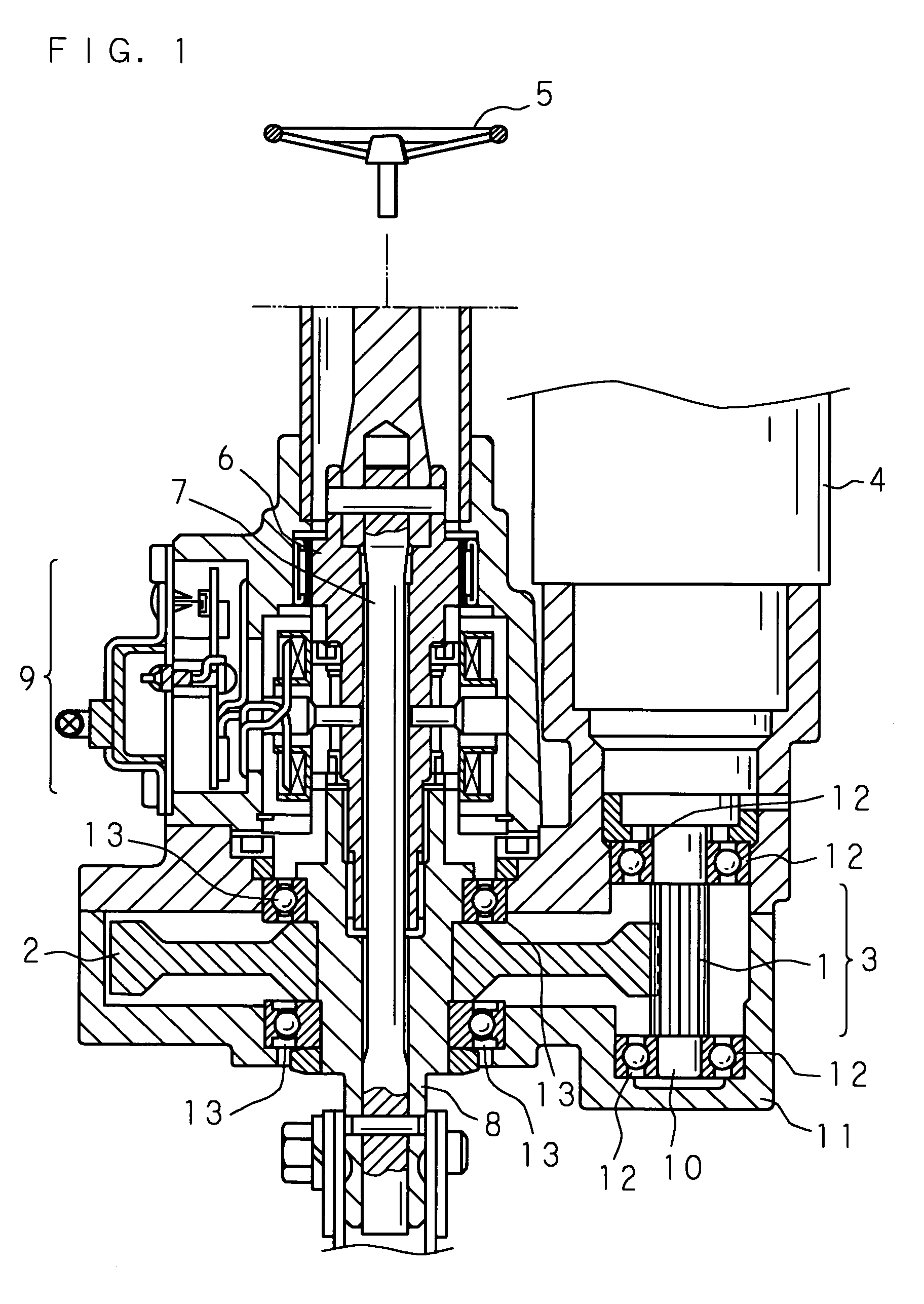
[0044]FIG. 1 is a sectional view as seen on a plane including a central axis of a steering shaft and a rotation axis of an electric motor showing an illustrative configuration of an electric power steering device utilizing a reduction gear unit in accordance with an embodiment of the present invention. As shown in FIG. 1, the electric power steering device transmits steering torque acted on a steering wheel 5 to the side of steering wheels by way of a steering shaft 6, a torsion bar 7, and a gear shaft 8 and also delivers supplemental torque generated by an electric motor 4 to the side of tire wheels by way of the gear shaft 8.

[0045]The steering shaft 6 is connected to the steering wheel 5, constituting an element of a torque transmission means which transmits steering torque acted on the steering wheel 5 to the side of tire wheels.

[0046]The torsion bar 7 connects the steering shaft 6 to the gear shaft 8 and generates a torsional deformation and a relative displacement between rotat...


PUM


Abstract

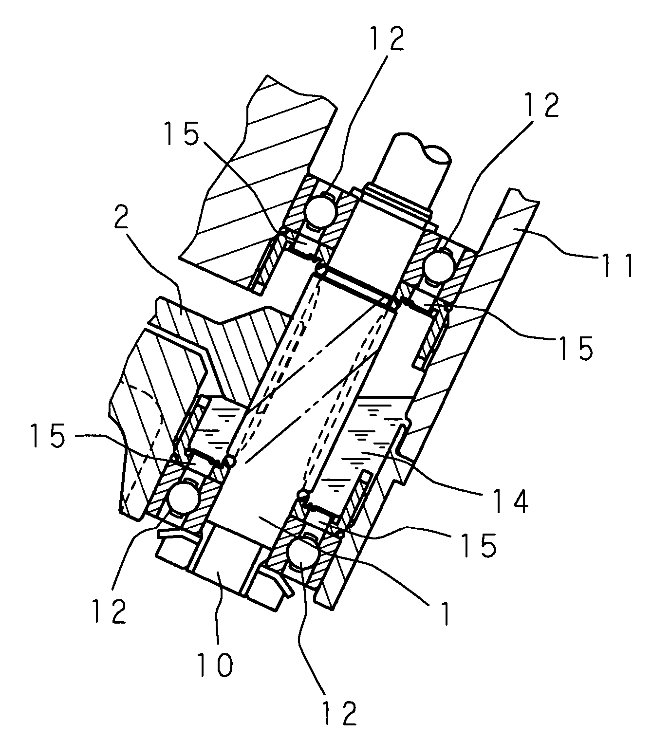
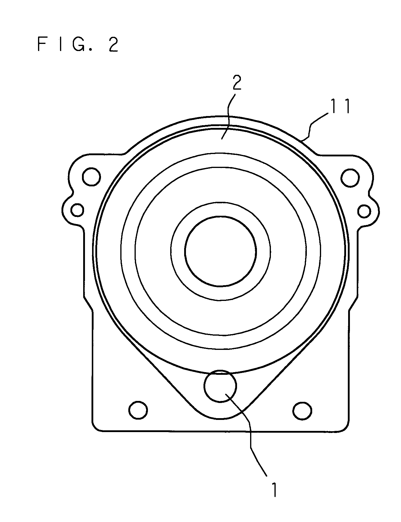
A reduction gear unit capable of reducing vibrations caused by gear rattle, while permitting some degree of backlash in a pair of gears, is provided. A reduction gear unit is so configured that a pinion shaft and a main gear shaft are disposed in parallel to each other, and a pinion 1 mounted on the pinion shaft and a main gear 2 mounted on the main gear shaft are arranged to mesh with each other, so as to transmit a rotation of the pinion shaft to the main gear shaft, and includes a housing 11 that encloses the pinion 1 and the main gear 2, where the housing 11 has an inner surface whose width, in a cross section perpendicular to an axial direction of the pinion shaft and the main gear shaft, perpendicular to an imaginary line that connects centers of the pinion shaft and the main gear shaft evenly increases from a pinion side toward a main gear side between ends of arcuate regions respectively enclosing the main gear and the pinion. The housing 11 contains a resin lubricant of a sufficient amount for immersing a part of a portion where the pinion 1 and the main gear 2 mesh with each other.

Description

CROSS-REFERENCE TO RELATED APPLICATIONS[0001]This application is the national phase under 35 U.S.C. § 371 of PCT International Application No. PCT / JP2004 / 012348 which has an International filing date of Aug. 27, 2004 and designated the United States of America.TECHNICAL FIELD[0002]The present invention relates to a reduction gear unit capable of reducing a speed of supplemental torque that assists a steering operation, and transmitting the reduced speed to a steering shaft.BACKGROUND ART[0003]In recent years, electric power steering devices employing an electric motor in a steering assist mechanism are commonly employed as steering devices for automobiles. Such a conventional steering device typically transmits a rotational torque generated by the electric motor to a steering column as supplemental torque by way of a worm gear.[0004]However, because transmission efficiency of worm gears is in such a low range as 60% to 80% in general, a larger output torque from the electric motor i...

Claims


Application Information

Patent Timeline
Patent Type & Authority Patents(United States)
IPC IPC(8): F16H57/04B62D5/04F16H1/06F16H57/02F16H57/021F16H57/028F16H57/029F16H57/03
CPCB62D5/0412F16H57/0493F16H57/0457F16H1/06Y10T74/19991
Inventor KUROUMARU, YOSHIKAZUNAKANO, SHIROUNISHIZAKI, KATSUTOSHI
Owner JTEKT CORP
Learn More