Control system and vehicle

a control system and vehicle technology, applied in the field of control systems, can solve the problems of unnatural feeling, reduced engine brake power, and inability to realize the reduction of vehicle speed, and achieve the effect of smooth stop and easy adjustmen

Inactive Publication Date: 2012-09-04
YAMAHA MOTOR CO LTD
View PDF12 Cites 0 Cited by
  • Summary
  • Abstract
  • Description
  • Claims
  • Application Information

AI Technical Summary

Benefits of technology

[0008]In order to overcome the problems described above, preferred embodiments of the present invention provide a control system that can smoothly decelerate a vehicle while preventing deterioration of the driving feeling of the vehicle by a brake operation and a vehicle having the same.
[0025]Also, when a brake operation by the driver is detected by the second detector after the occurrence of the control failure of the electronically-controlled throttle valve, the controller corrects the target acceleration such that the absolute value of the target acceleration becomes larger. In this case, the output of the engine is decreased such that the vehicle runs with the corrected target acceleration. Thus, even when the driver performs a brake operation during the deceleration control of the vehicle, the reduction of the engine brake power is prevented. As a result, the deterioration of the driving feeling of the vehicle is prevented during the deceleration.

Problems solved by technology

In this case, the driver cannot realize the reduction of the speed of the vehicle by the driver's own brake operation, and will feel unnatural.
Also, when the amount of the brake operation by the driver is large, the engine brake power may become zero and the torque may be transmitted from the engine to the drive wheel.
In this case, the deceleration of the vehicle decreases, and the vehicle may not be smoothly decelerated.
The inventors have found from such considerations that with the control operation of the engine control device of JP 2006-336640 A, the driver may feel uncomfortable due to the different deceleration, which could cause the driving feeling to be degraded.
In this control system, when a control failure of the electronically-controlled throttle valve of the vehicle occurs, the control failure is detected by the first detector.

Method used


Image

  • Control system and vehicle
  • Control system and vehicle
  • Control system and vehicle

Examples


Embodiment Construction

[0035]Now, a vehicle equipped with a control system according to preferred embodiments of the present invention will be described referring to the drawings. The description below describes a motorcycle as an example of the vehicle. Also, as an example of the control system, the description below describes a semi-automatic speed change control system that automatically performs the gear change of the transmission on the basis of a shifting operation by the driver.

(1) OUTLINE OF STRUCTURE OF MOTORCYCLE

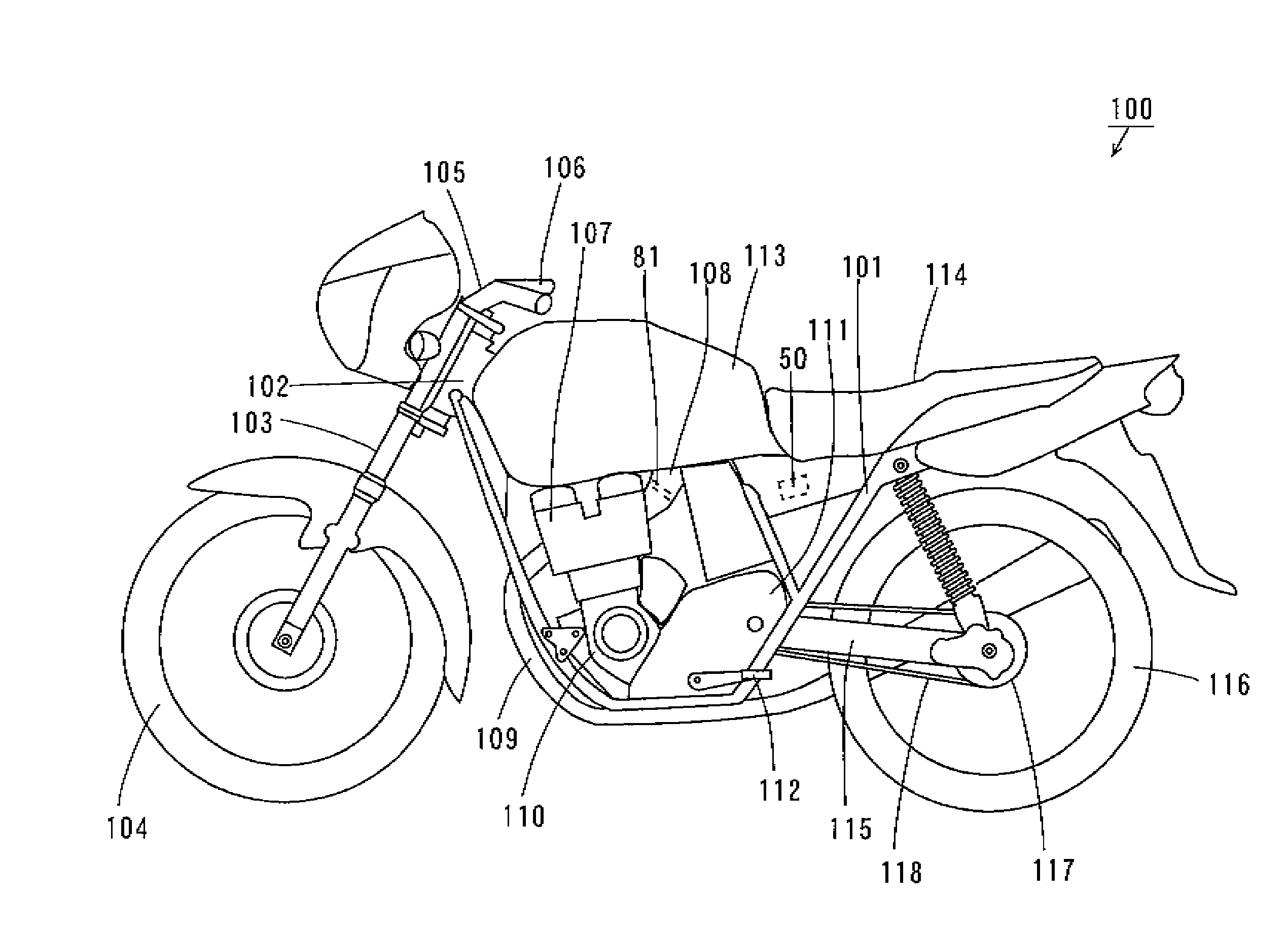
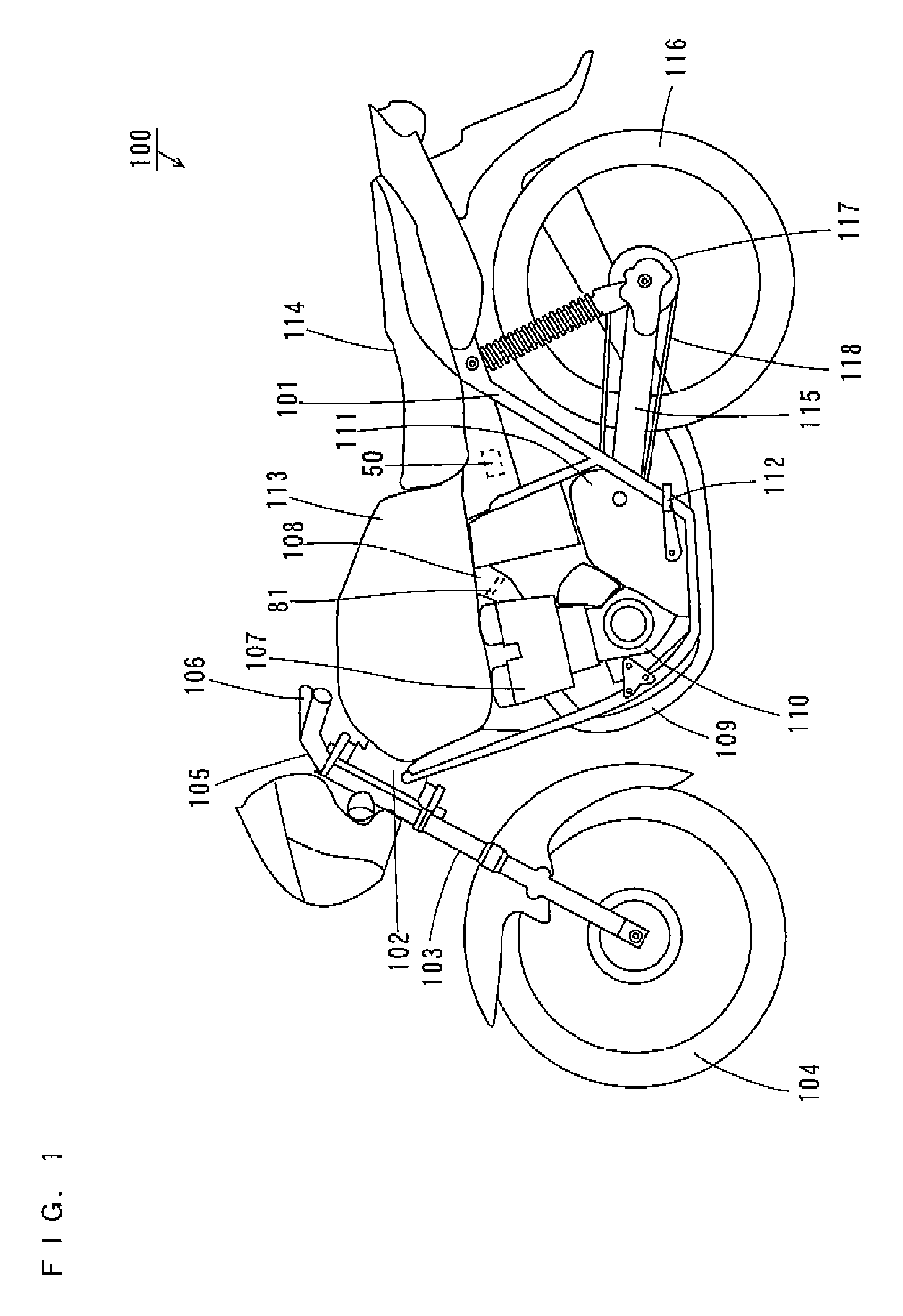
[0036]FIG. 1 is a schematic side view illustrating a motorcycle according to this preferred embodiment.

[0037]In the motorcycle 100 of FIG. 1, a head pipe 102 is provided at the front end of a body frame 101. A front fork 103 is attached to the head pipe 102 in such a way that it can turn from side to side. A front wheel 104 is rotatably supported at the lower end of the front fork 103. A handle 105 is provided at the upper end of the head pipe 102.

[0038]The handle 105 is equipped with an...


PUM


Abstract

A control system for a vehicle includes a CPU, a throttle sensor, a brake sensor, and fuel injectors. When the CPU detects a control failure of the throttle valve with a value detected by the throttle sensor, the CPU adjusts the output of the engine by controlling the fuel injectors such that the motorcycle runs with a previously set negative target acceleration. Also, when the CPU detects a brake operation by the driver with the brake sensor after the occurrence of the control failure, the CPU corrects the target acceleration such that the deceleration of the motorcycle becomes larger. Then, the CPU adjusts the output of the engine such that the motorcycle runs with the corrected target acceleration.

Description

BACKGROUND OF THE INVENTION[0001]1. Field of the Invention[0002]The present invention relates to a control system for adjusting the output of an engine and to a vehicle having the same.[0003]2. Description of the Related Art[0004]Conventionally, in order to enable high-level engine control, vehicles equipped with electronically-controlled throttle systems have been developed. In such an electronically-controlled throttle system, a sensor detects the amount of accelerator operation by the driver, and an ECU (Electronic Control Unit) adjusts the opening of the throttle valve according to the detected amount of accelerator operation.[0005]For a vehicle equipped with such an electronically-controlled throttle device, it is desired that the vehicle be designed by considering that the throttle valve might become unable to be properly controlled. Specifically, it is preferable to construct a control system that can smoothly decelerate the vehicle in the event of a control failure of the th...

Claims


Application Information

Patent Timeline
Patent Type & Authority Patents(United States)
IPC IPC(8): B60T7/12G05D1/00
CPCF02D11/107F02D41/12B60W2540/12B60W2720/106B60Y2200/12F02D41/023Y10T477/6936F02D2011/102F02D2200/0404F02D2041/227F02D2200/602Y10T477/688Y10T477/693F02D41/34
Inventor ARAI, KATSUHIRO
Owner YAMAHA MOTOR CO LTD
Why Eureka
Try Eureka