Control device of vehicle

a technology of control device and vehicle, which is applied in the direction of electrical control, process and machine control, instruments, etc., can solve the problems of suppression of rubber band feel, and suppression of sluggish feeling, so as to suppress the deterioration of driving feeling, suppress the feeling of sluggishness, and suppress the feeling of rubber band feel

Active Publication Date: 2022-08-02
TOYOTA JIDOSHA KK
View PDF3 Cites 0 Cited by
  • Summary
  • Abstract
  • Description
  • Claims
  • Application Information

AI Technical Summary

Benefits of technology

[0004]When the engine output changes slowly with respect to the request engine output, the vehicle speed can be increased as the engine speed increases during vehicle acceleration. In this way, so-called rubber band feel is suppressed, and thus driving feeling is improved. However, in an engine having a turbocharger, the response delay of the turbocharging pressure and the slow change of the engine output are combined due to the response of the turbocharging pressure to cause a feeling of sluggish, which may rather result in deterioration of driving feeling.
[0005]The disclosure has been made in view of the above circumstances, and an object of the disclosure is to provide a control device for a vehicle capable of suppressing a feeling of sluggish while suppressing deterioration of driving feeling according to the response of a turbocharging pressure.
[0010]According to the aspect of the control device of the disclosure, (a) a target operating point setting unit configured to calculate a request driving force requested for the vehicle based on an accelerator operation amount, and set a target operating point of the engine through a slow change process for obtaining an engine output that slowly changes with respect to a request engine output achieving the calculated request driving force based on the calculated request driving force, (b) a smoothing factor setting unit configured to change a smoothing factor used for the slow change process according to an amount of change in a turbocharging pressure in the engine and set the smoothing factor to a smaller value when the amount of change in the turbocharging pressure is smaller than when the amount of change in the turbocharging pressure is larger, and (c) a drive controller configured to control the engine and the continuously variable transmission such that the operating point of the engine becomes the target operating point are included. When the amount of change in the turbocharging pressure is large, the smoothing factor used for the slow change process is set to a relatively large value, resulting in suppression of the rubber band feel, and when the amount of change in the turbocharging pressure is small, the smoothing factor used for the slow change process is set to a relatively small value, resulting in suppression of the feeling of sluggish. In this way, the rubber band feel is suppressed by the slow change process, thereby making it possible to suppress the deterioration of the driving feeling and suppress the feeling of sluggish when the amount of change in the turbocharging pressure is small.
[0011]According to the aspect of the control device of the disclosure, the smoothing factor setting unit may be further configured to change the smoothing factor according to an amount of change in an engine speed and set the smoothing factor to a larger value when the amount of change in the engine speed is larger than when the amount of change in the engine speed is smaller. When the amount of change in the engine speed is large, the rubber band feel tends to be remarkable, but when the amount of change in the engine speed is large, the smoothing factor is set to a relatively large value, thereby suppressing the rubber band feel and thus improving the driving feeling.
[0012]According to the aspect of the control device of the disclosure, the smoothing factor setting unit may be further configured to change the smoothing factor according to an amount of change in the request driving force and set the smoothing factor to be a larger value when the amount of change in the request driving force is larger than when the amount of change in the request driving force is smaller. When the amount of change in the request driving force is large, the vehicle speed is remarkably increased and thus the rubber band feel is likely to occur. However, since the smoothing factor is set to a relatively large value when the amount of change in the request driving force is large, the rubber band feel is suppressed and thus the driving feeling is improved.
[0013]According to the aspect of the control device of the disclosure, (a) the vehicle may include a rotating machine connected to the power transmission path, and (b) the smoothing factor setting unit may be further configured to change the smoothing factor according to a torque assist rate of the rotating machine and set the smoothing factor to be a larger value when the torque assist rate is smaller than when the torque assist rate is larger. When the torque assist rate of the rotating machine is smaller, the change in the operating point of the engine is larger when the torque assist rate is larger, and as a result, a rubber band feel is likely to occur. When the torque assist rate is smaller, the smoothing factor is set to a large value than when the torque assist rate is larger, and thus, the operating point of the engine can be slowly changed. In this way, the rubber band feel is suppressed and thus the driving feeling is improved.

Problems solved by technology

However, in an engine having a turbocharger, the response delay of the turbocharging pressure and the slow change of the engine output are combined due to the response of the turbocharging pressure to cause a feeling of sluggish, which may rather result in deterioration of driving feeling.
When the amount of change in the turbocharging pressure is large, the smoothing factor used for the slow change process is set to a relatively large value, resulting in suppression of the rubber band feel, and when the amount of change in the turbocharging pressure is small, the smoothing factor used for the slow change process is set to a relatively small value, resulting in suppression of the feeling of sluggish.
When the torque assist rate of the rotating machine is smaller, the change in the operating point of the engine is larger when the torque assist rate is larger, and as a result, a rubber band feel is likely to occur.

Method used


Image

  • Control device of vehicle
  • Control device of vehicle
  • Control device of vehicle

Examples


first embodiment

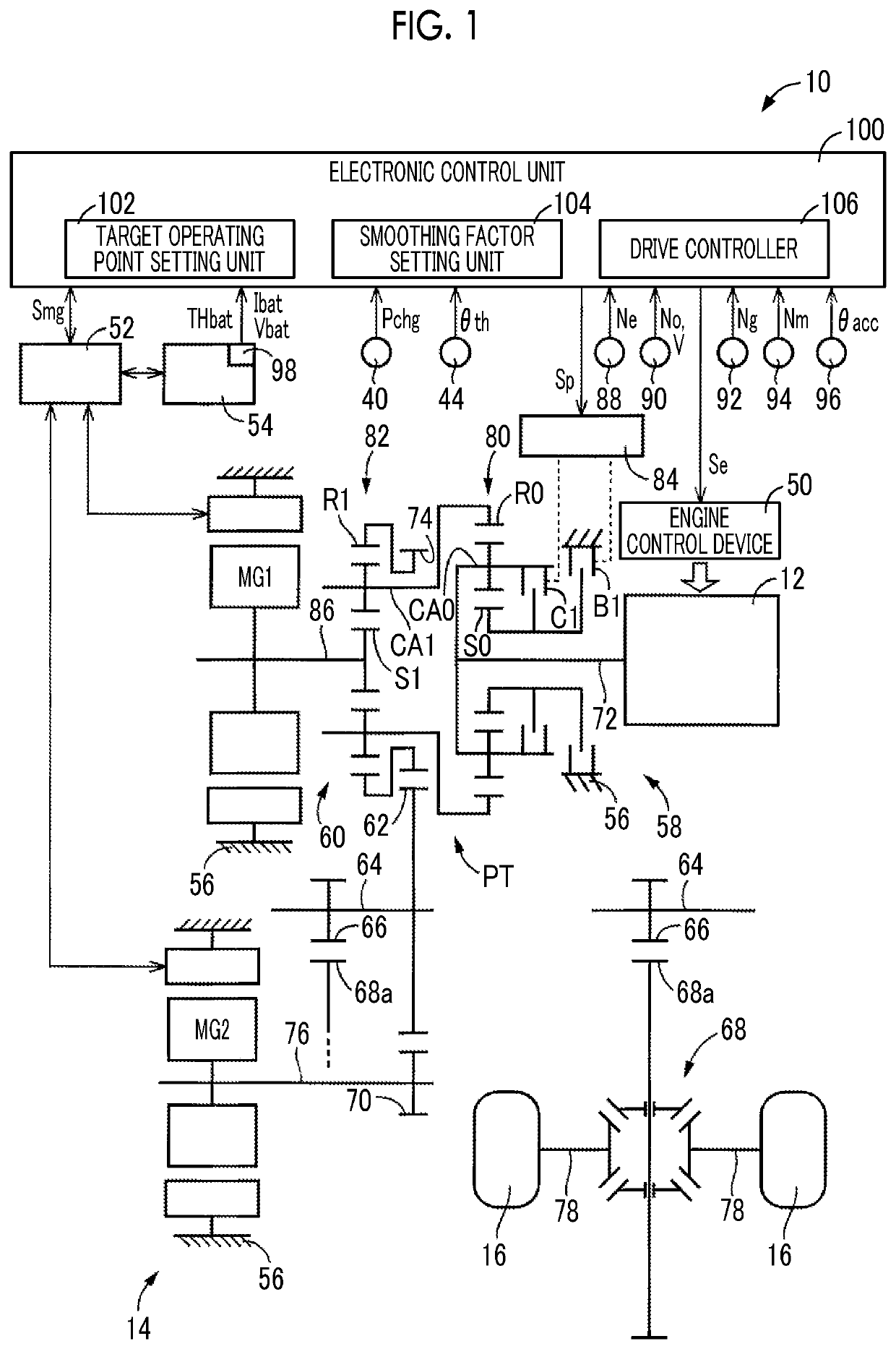
[0030]FIG. 1 is a schematic configuration diagram of a vehicle 10 on which an electronic control unit 100 according to the disclosure is mounted, and is a functional block diagram illustrating main parts of a control functions for various controls in the vehicle 10. The vehicle 10 is a hybrid vehicle including an engine 12, a first rotating machine MG1, a second rotating machine MG2, a power transmission device 14, and drive wheels 16.

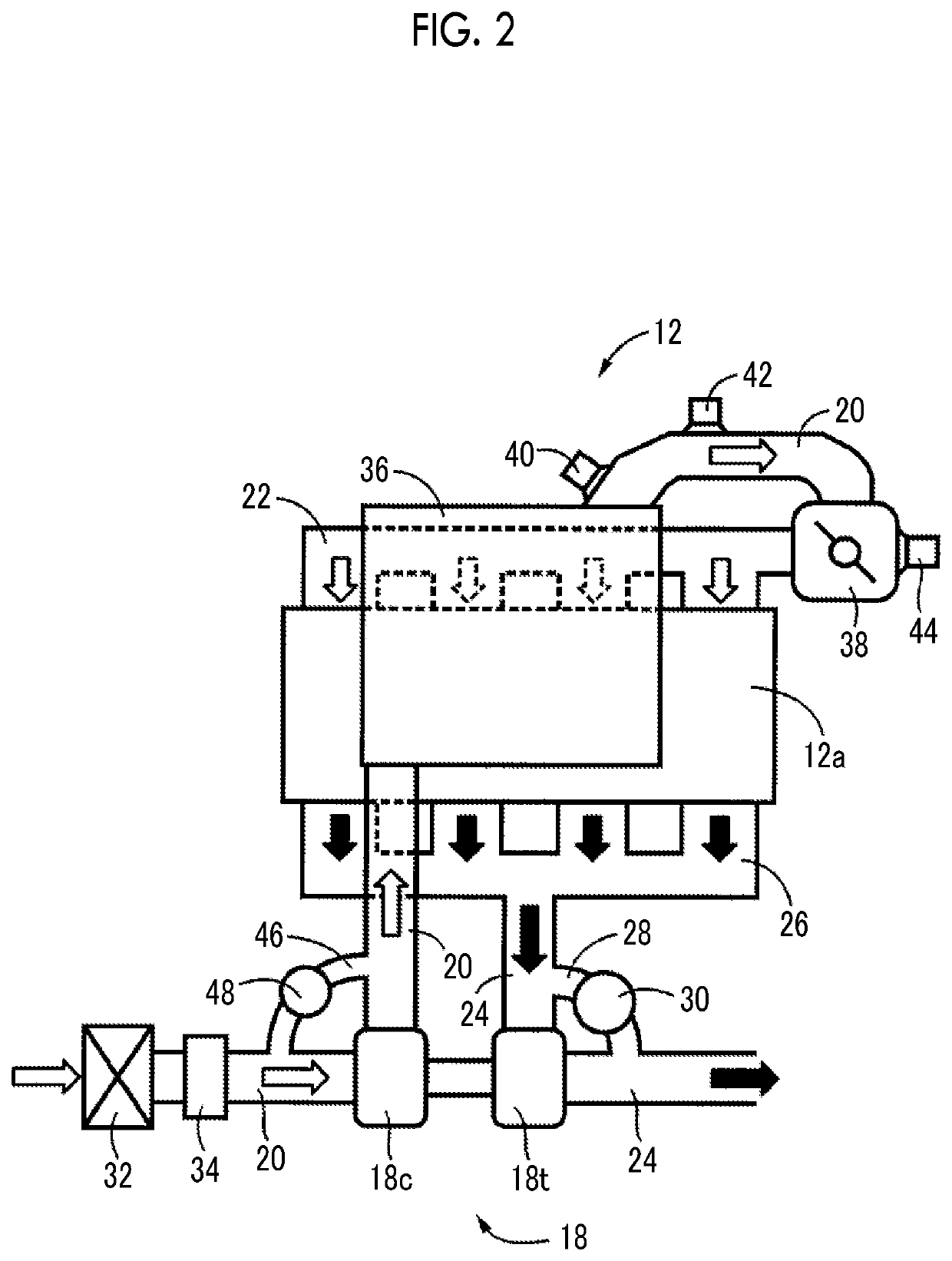
[0031]FIG. 2 is a diagram illustrating a schematic configuration of the engine 12 illustrated in FIG. 1. The engine 12 is a power source for causing the vehicle 10 to travel and is a known internal combustion engine such as a gasoline engine or a diesel engine having a turbocharger 18, that is, an engine with a turbocharger 18. An intake pipe 20 is provided in an intake system of the engine 12, and the intake pipe 20 is connected to an intake manifold 22 attached to an engine main body 12a. An exhaust pipe 24 is provided in an exhaust system of the eng...

second embodiment

[0131]In the above-described second embodiment, the one-way clutch F0 is exemplified as the lock mechanism capable of fixing the carrier CA1 in a non-rotatable state, but the present disclosure is not limited to this mode. This lock mechanism may be an engagement device such as a meshing type clutch, a hydraulic friction engagement device such as a clutch and a brake, a dry engagement device, an electromagnetic friction engagement device, a magnetic powder clutch, for example, for selectively connecting the input shaft 272 and the case 256. Alternatively, the vehicle 210 does not necessarily need to include the one-way clutch F0.

[0132]In the first to third embodiments, the turbocharger 18 is a known exhaust turbine type turbocharger, but is not limited to this mode. For example, the turbocharger 18 may be a mechanical pump type turbocharger that is rotationally driven by an engine or an electric motor. Further, as the turbocharger, an exhaust turbine type turbocharger and a mechanic...


PUM


Abstract

An electronic control unit of a vehicle includes (a) a target operating point setting unit that calculates a request driving force requested for a vehicle, and set a target engine operating point through a slow change process for obtaining an engine output that slowly changes with respect to a request engine output implementing the request driving force, (b) a smoothing factor setting unit that changes a smoothing factor used for the slow change process according to an amount of change in a turbocharging pressure in the engine and sets the smoothing factor to a smaller value when the amount of change in the turbocharging pressure is smaller than when the amount of change in the turbocharging pressure is larger, and (c) a drive controller that controls the engine and the continuously variable transmission such that the engine operating point is the target engine operating point.

Description

CROSS-REFERENCE TO RELATED APPLICATION[0001]This application claims priority to Japanese Patent Application No. 2019-140349 filed on Jul. 30, 2019, incorporated herein by reference in its entirety.BACKGROUND1. Technical Field[0002]The disclosure relates to a control device for a vehicle in which power output from an engine having a turbocharger is transmitted to drive wheels through a continuously variable transmission.2. Description of Related Art[0003]A control device of a vehicle is known that sets a target operating point of an engine through a slow change process for obtaining an engine output that slowly changes with respect to a request engine output achieving a request driving force based on the request driving force calculated based on an accelerator operation amount. One example thereof is a control device of a vehicle disclosed in Japanese Unexamined Patent Application Publication No. 2009-166659 (JP 2009-166659 A). JP 2009-166659 A discloses that a slow change process is...

Claims


Application Information

Patent Timeline
Patent Type & Authority Patents(United States)
IPC IPC(8): G05D1/08B60R16/03
CPCG05D1/0891B60R16/03B60W10/06B60W10/08B60W10/101B60W20/40B60W30/1882F02D41/0007F02D29/02B60W2510/0638B60W2510/0633B60W2510/0657B60W2710/0677B60W2710/0666B60W2710/0644Y02T10/62B60K6/445B60W2540/10B60W2510/0652B60W2510/083B60W20/15
Inventor HIASA, YASUHIROTABATA, ATSUSHIOKUDA, KOICHIMATSUBARA, TOORU
Owner TOYOTA JIDOSHA KK
Why Eureka
Try Eureka