
Method and a mobile station for configuring a base station

a mobile station and base station technology, applied in the field of configuring base stations, can solve the problems of time-consuming prior art methods and time-consuming methods for configuring stations for specific installation areas

Inactive Publication Date: 2005-09-13
WSOU INVESTMENTS LLC
View PDF8 Cites 47 Cited by
  • Summary
  • Abstract
  • Description
  • Claims
  • Application Information

AI Technical Summary

Benefits of technology

[0011]The present invention allows configuring of an indoor base station with less planning than according to prior art methods. Suitable places for the stations are first located by a rough inspection of the building, whereafter the stations are installed and wired by an installation engineer. The base stations are configured using a mobile communication means for both scanning the frequencies and communicating the results of the scanning to the base station. An advantage of the invention is, that the invention allows obtaining free frequencies on-site for the base stations to operate on and after selecting a sufficient amount of frequencies, uploading the selections to the base stations. Theoretical calculations are not necessarily needed for finding frequencies that are free enough from the effect of the external network outside the building. The means used for scanning and selecting the frequencies can be made easy to use. In an advantageous embodiment of the invention, no manual setting of frequencies for the base station is needed because of automated data exchance between the scanning means and the base station. Configuring of a base station with the inventive method and arrangement is much faster compared to prior art methods. Configuration time can be shortened as long as about 8 days according to the prior art methods to as low as 1 hour using the inventive method.

Problems solved by technology

One problem in the configuration of base stations according to the prior art is the time required to configure a station for the specific installation area, for example an apartment in a building.
The prior art methods used are time consuming, since simulation is typically used for finding correct operation parameters for the base station.

Method used


Image

  • Method and a mobile station for configuring a base station
  • Method and a mobile station for configuring a base station
  • Method and a mobile station for configuring a base station

Examples


Embodiment Construction

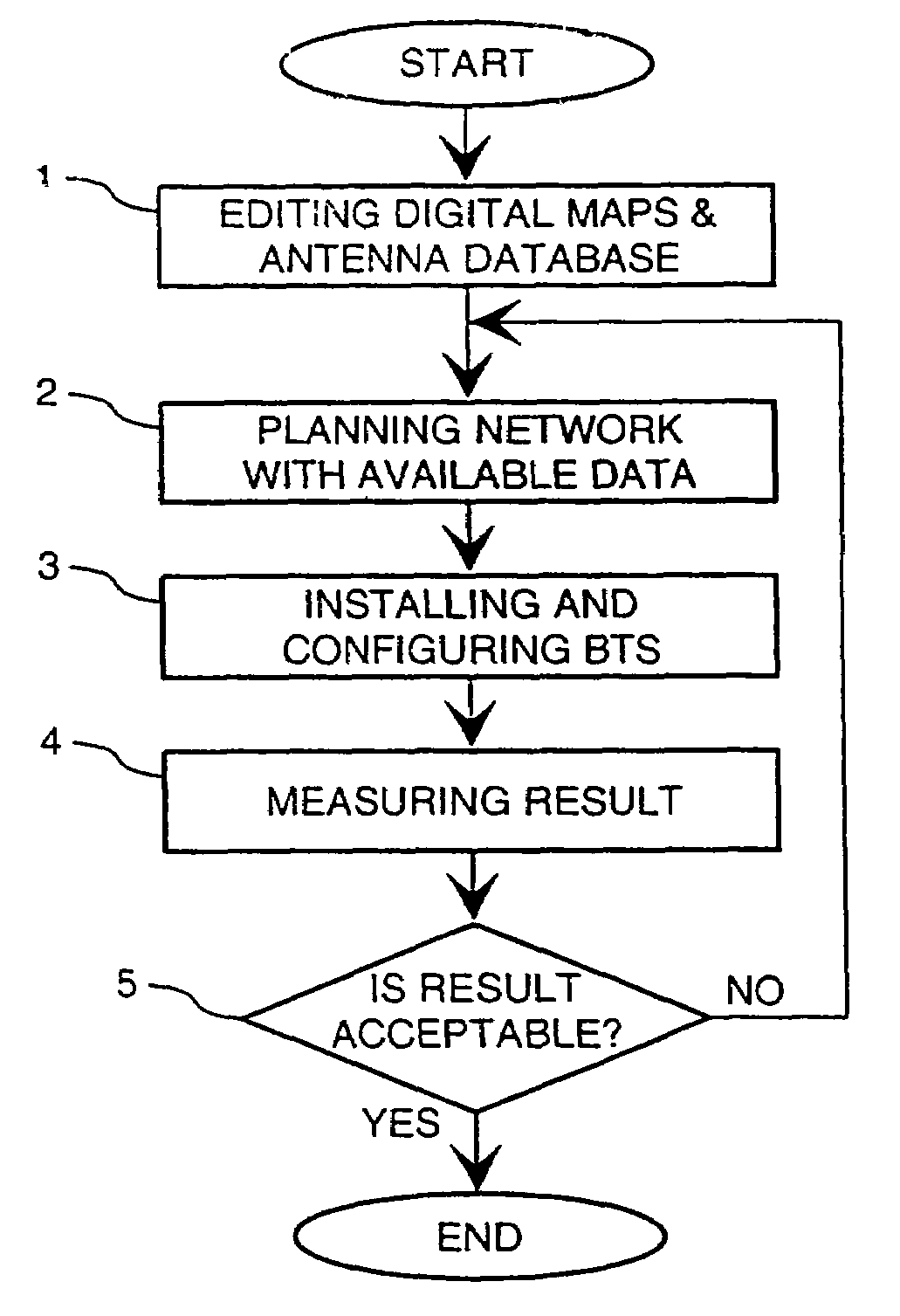
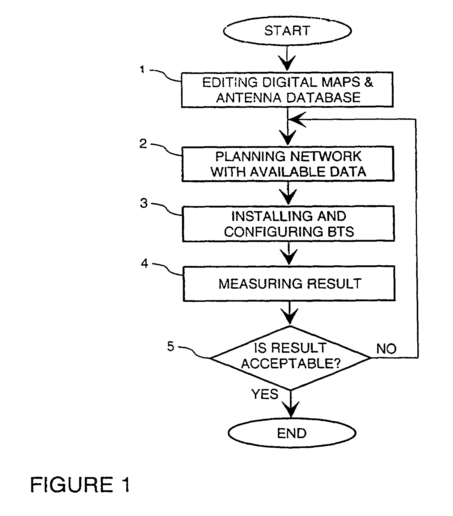
[0018]FIG. 1 was described previously in connection with description of prior art.

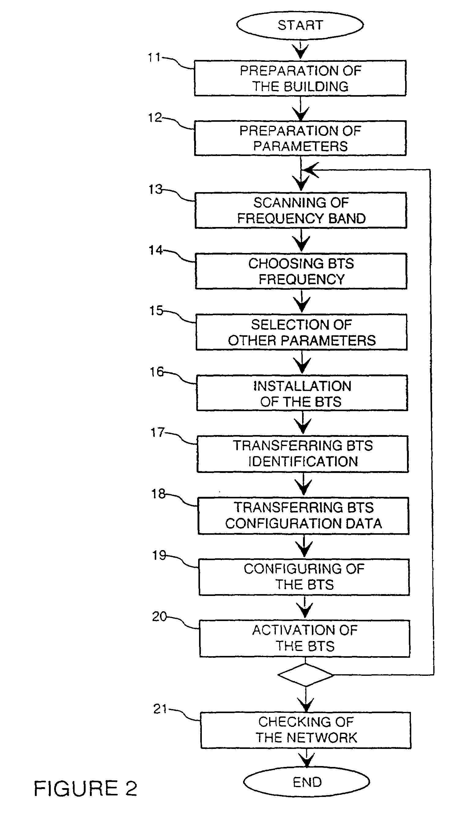
[0019]In one advantageous embodiment of the invention, installation of an indoor cellular network proceeds in the following four phases. This embodiment is illustrated by FIG. 2.

1. Preparation of the Building

[0020]In the first phase 11, the building is roughly inspected, if possible. Based on the inspection and maps of the building, preliminary locations for base stations are located. Preferably, a slightly larger number of preliminary locations are preplanned than will actually be used. Some locations are preferably prepared near entrances to the building to form a gateway to surrounding cellular network. Sufficient overlap with the surrounding network is necessary to allow smooth handover of connections from the in-building network to the surrounding network and vice versa. A data transmission network is constructed in the building based on these preplanned preliminary locations. For example, existin...


PUM


Abstract

The invention relates to a method and an arrangement for configuring an indoor base station for a cellular mobile telecommunications network. According to an advantageous embodiment of the inventive method, a mobile communications means is used to scan possible transmission frequencies on-site to find out free frequencies to operate on, and to transmit the results of scanning of the frequencies to the indoor base station and to choose proper parameters for the indoor base station. An arrangement according to an advantageous embodiment of the invention comprises an indoor Base Transceiver Station, mobile communications means for scanning frequencies and to find free frequencies and a Base Station Controller for controlling the base station.

Description

CROSS REFERENCES TO RELATED APPLICATIONS[0001]This is a national stage application under 35 U.S.C. §371 of international stage PCT application No. PCT / FI99 / 00572, filed on Jun. 29, 1999. Priority is claimed under 35 U.S.C. §119(a) and 35 U.S.C. §365(b) from Finnish Patent Application No. 981491, which was filed in Finland on Jun. 29, 1998, and from which priority was properly claimed in the aforementioned international stage application.BACKGROUND OF THE INVENTION[0002]1. Field of the Invention[0003]The present invention is directed generally to configuring base station in a cellular telecommunication system and specifically to a method for configuring an indoor cellular base station and to a system for implementing this method.[0004]2. Description of the Related Art[0005]In FIG. 1 a known method to install and configure cellular Base Transceiver Stations is shown. Digital maps of the building and a database describing positions of external antennas are first edited in step 1. The i...

Claims


Application Information

Patent Timeline
IPC IPC(8): H04Q7/36H04Q7/30H04Q7/32H04Q7/34H04W16/14H04W16/18
CPCH04W16/14H04W16/18
Inventor ESSER, ALEXWESBY, PHILIPTOSSAVAINEN, TEPPOSINIVAARA, HASSEHIRVONEN, HEIKKISUONVIERI, JUKKAJUUTI, MATTI
Owner WSOU INVESTMENTS LLC
Learn More