Combination dump and spreader apparatus

a technology of spreader and dump, which is applied in the direction of centrifugal wheel fertilisers, ways, constructions, etc., can solve the problems of deformation in the assembly, cumbersome installation of the spreader for a dealer, and difficult adjustment of the spreader

Inactive Publication Date: 2005-09-20
HENDERSON PRODS
View PDF11 Cites 24 Cited by
  • Summary
  • Abstract
  • Description
  • Claims
  • Application Information

AI Technical Summary

Benefits of technology

[0015]In another aspect of the invention, the vehicle includes a diverter chute that is operably arranged with the conveyor assembly to receive materials from the conveyor assembly. The chute includes a body that defines a passageway and a panel that is movable between a first position and a second position. The panel allows material to move through the chute to the spreader when the panel is in the first position. The panel prevents material from moving through the chute when the panel is in the second position.

Problems solved by technology

The former situation typically results in a deposit of the material into a conventional spreader mounted on the rear of the vehicle.
While existing combination dump and spreader bodies provide many desirable features and advantages, there remain certain problems with these combination bodies.
The mounting of the spreaders can be cumbersome for a dealer to perform.
Furthermore, the spreader can be difficult to adjust once it has been mounted.
In use, the feed gate assembly undergoes considerable stress, which can cause deformation in the assembly.

Method used


Image

  • Combination dump and spreader apparatus
  • Combination dump and spreader apparatus
  • Combination dump and spreader apparatus

Examples


Embodiment Construction

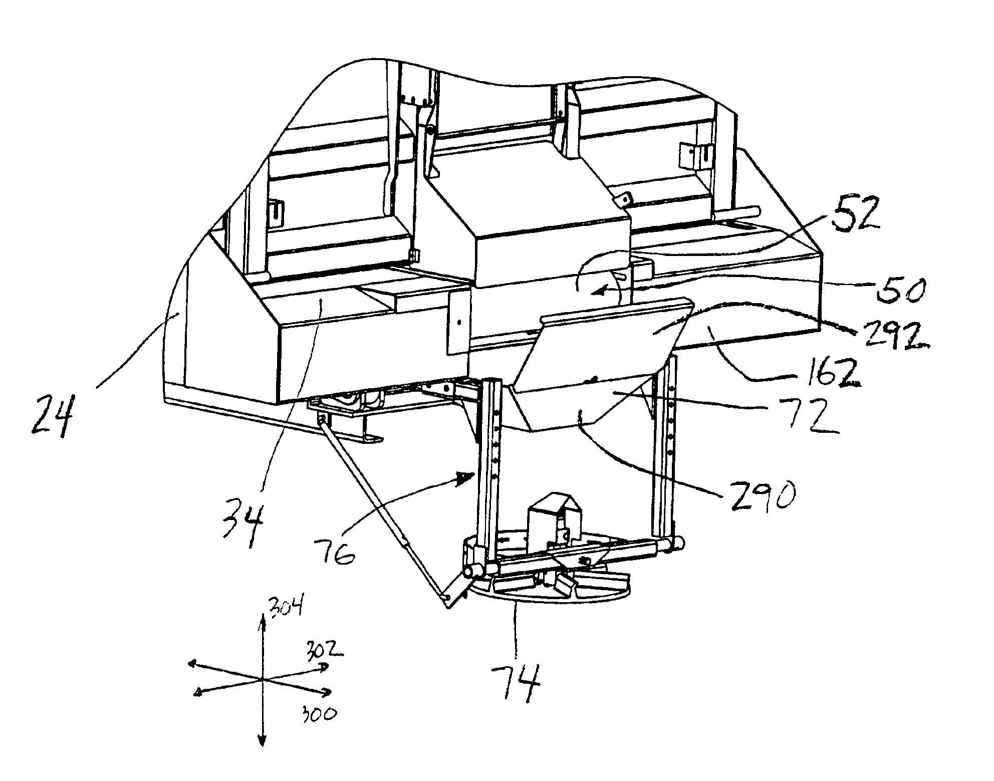
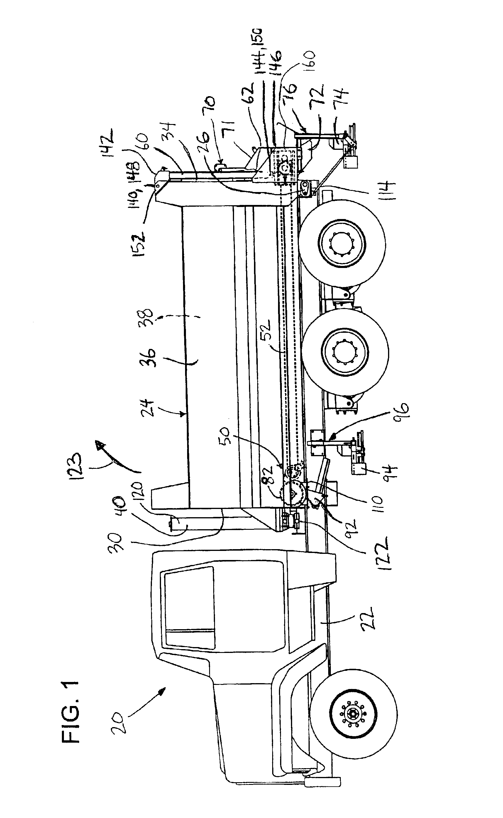
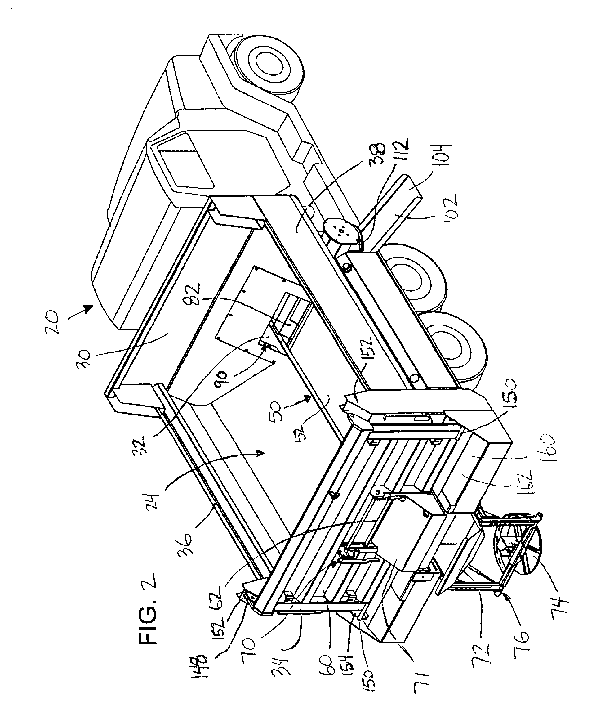
[0043]Turning now to the drawings, there is shown in FIG. 1 an illustrative vehicle 20 including a combined dump and spreader apparatus, also known as a combination body, for dumping and spreading materials in accordance with the present invention. The present inventive vehicle shown and described herein improves upon the vehicle shown and described in U.S. patent application Ser. No. 09 / 256,053, filed Feb. 23, 1999, and entitled “Combination Dump And Spreader Apparatus,” which is incorporated herein by reference in its entirety.

[0044]Referring to FIGS. 1-3, the vehicle 20 includes a chassis 22 and a combination body 24 for holding materials and for selectively dumping and spreading materials. The body 24 is pivotally mounted to the chassis 22 at a hinge 26. The body 24 includes a front end 30 having an opening 32, a rear end 34, and first and second side walls 36, 38. A hoist 40 is provided which extends between the body 24 and the chassis 22 for pivoting the body about the hinge 2...


PUM


Abstract

A vehicle is disclosed which includes a chassis and a combination body for selectively dumping and spreading materials. A hoist is provided which extends between the body and the chassis for pivoting the body. A conveyor assembly for selectively conveying materials from the body is also included. A tailgate is pivotally connected to the body and has an opening therein to permit material to be transported therethrough. A rear feed gate assembly for selectively covering the opening of the tailgate is provided. The vehicle includes a rear diverter chute that is operably arranged with the conveyor assembly to direct the materials to a rear spreader. A front feed gate assembly for selectively covering an opening of a front end of the body is provided. First and second side chutes are operably arranged with the conveyor assembly to direct materials to a side spreader and a surface, respectively.

Description

CROSS-REFERENCE TO RELATED APPLICATIONS[0001]This patent application claims the benefit of priority to U.S. Provisional Application No. 60 / 362,565, filed Mar. 7, 2002, entitled “Combination Dump and Spreader Apparatus,” which is incorporated in its entirety herein by this reference.FIELD OF THE INVENTION[0002]The present invention relates generally to a combination dump and spreader apparatus which, when mounted onto a vehicle chassis, provides for selective dumping and spreading of material from the apparatus, advantageously granular material such as sand, salt and the like, onto surfaces such as roadways.BACKGROUND OF THE INVENTION[0003]Many types of vehicles are available with an apparatus mounted thereon which provide for both the dumping and spreading of material, such as sand, salt, gravel, asphalt and the like, onto a surface. One type of apparatus which provides this dual functionality is commonly referred to as a combination body. Combination bodies are so named because the...

Claims


Application Information

Patent Timeline
Patent Type & Authority Patents(United States)
IPC IPC(8): E01C19/00E01C19/20
CPCE01C19/203E01C2019/2075E01C2019/2085E01C2019/2095
Inventor HOLLINRAKE, MARK S.WARD, MART E.BURKEN, WADE J.UNGERER, GLENN
Owner HENDERSON PRODS
Why Eureka
Try Eureka