Inkjet printing apparatus

Inactive Publication Date: 2005-09-20
CANON KK
View PDF12 Cites 2 Cited by
  • Summary
  • Abstract
  • Description
  • Claims
  • Application Information

AI Technical Summary

Benefits of technology

[0025]The invention has been made to solve such problems, and it is an object of the invention to provide an inkjet printing apparatus in which a suitable process is taken depending on changes in physical properties and chemical properties of an ink to suppress wasteful consumption of the ink and to perform stable printing at a low cost.

Problems solved by technology

When such an ink including particles having greater diameters or settlings is supplied to a printing head, the ink can clog ink ejection openings and liquid passages in communication therewith to result in an ejection failure.
In the case of a printing head in which a heater is used to generate thermal energy as energy for ink ejection, such an ink can cause problems such as kogation or burning which can damage the printing head.
However, settlings can be deposited on the bottom while the cartridge is used for a long time while being replenished with ink repeatedly.
However, such inkjet printing apparatus have the following problems to be solved.
An ink supply unit and an agitating unit provided in an inkjet printing apparatus create problems such as an increase in the size of a main body of the apparatus and an increase in the manufacturing cost of the apparatus main body, and those units are therefore unsuitable for inkjet printing apparatus to be used in offices or homes.
Even when an ink supply unit serves also as an agitating unit, sufficient agitating performance cannot be achieved in a configuration in which an ink is held in the interior of an ink tank as a whole with a capillary force of an absorber in the form of a sponge or fabric.
This results in an indiscriminate increase in the running cost.
There will be an ink residue whose condition has changed in the ink chamber of the printing head, which can result in problems such as an ejection failure or disabled ejection in nozzles that are not in use.
Such an ejection failure is unlikely to occur at nozzles that are continuously used and is likely to occur at nozzles that are intermittently used (nozzles associated with inks that are not used for forming a certain image).
It is considered that the failure is likely to occur at the intermittently used nozzles because of a difference between quantities of heat accumulated at the continuously used nozzles and the intermittently used nozzles.

Method used


Image

  • Inkjet printing apparatus
  • Inkjet printing apparatus
  • Inkjet printing apparatus

Examples


first embodiment

[First Embodiment]

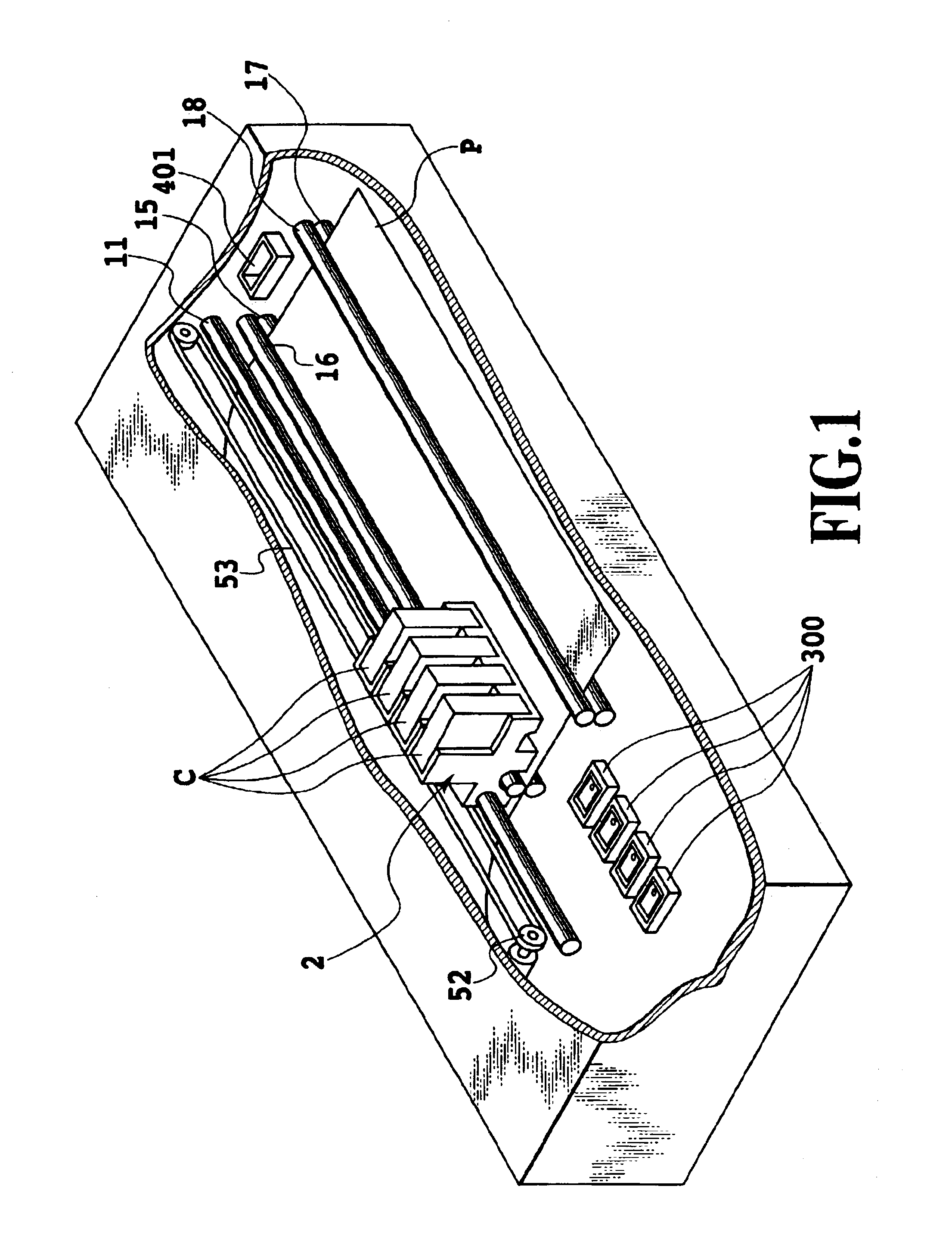
[0041]FIG. 1 is a perspective view showing a schematic configuration of a printing apparatus having a printing head for performing printing in accordance with the inkjet method that is a typical embodiment of the invention.

[0042]In FIG. 1, reference character C represents inkjet cartridges (hereinafter simply referred to as “cartridges”) that have an ink tank in an upper part thereof and a printing head in a lower part thereof and that is provided with a connector for receiving a signal for driving the printing head. Reference numeral 2 represents a carriage on which a plurality of cartridges C are mounted. Inks in different colors such as yellow, magenta, cyan, and black inks are contained in the ink tanks of the plurality of cartridges C, respectively. The carriage 2 is provided with connector holders that transmit signals for driving the printing heads of the respective cartridges C and that are electrically connected to the printing heads. In the example shown ...

second embodiment

[Second Embodiment]

[0084]Some ink tanks or some ink cartridges as shown in FIG. 3 provided by integrating an ink tank and a printing head have a memory section (e.g., an EEPROM) in which information on the manufacturing date is stored. In the present embodiment, as described below, an ink consumption threshold specific to an ink as described in the first embodiment is set for an ink cartridge in which information on the manufacturing date is stored, the threshold being variable depending on the time that has passed since the time of manufacture. This makes it possible to provide a printer with an improved running cost.

[0085]In the case of such an ink cartridge described above, the point in time when the cartridge is installed is used to trigger and an internal timer of a printing apparatus, for example, can calculate the time elapsed from the manufacture of the cartridge to the installation of the same.

[0086]FIG. 6 is a graph showing distributions of pigment densities of a pigment i...


PUM


Abstract

In an inkjet printing apparatus utilizing an inkjet head and an ink tank for supplying ink to the same, it is made possible to suppress any reduction in image quality attributable to changes in physical and chemical properties of the ink that occur during an elapsed time from the manufacture of the ink tank to the use of the same, thereby allowing images to be formed with high reliability and stability at a low running cost. The apparatus has a discharging unit for discharging the ink through a nozzle at the head and an ink detecting unit for detecting the consumption of the ink in the ink tank. The detected ink consumption is compared with a threshold for ink consumption appropriately determined based on the elapsed time, and control is performed such that the amount discharged by the discharging unit is increased when the ink has not been consumed sufficiently.

Description

[0001]This application claims priority from Japanese Patent Application No. 2002-222058 filed Jul. 30, 2002, which is incorporated hereinto by reference.BACKGROUND OF THE INVENTION[0002]1. Field of the Invention[0003]The present invention relates to an inkjet printing apparatus and, more particularly, to a printing apparatus using an inkjet printing method in which images are formed by forming ink dots on a printing medium.[0004]2. Description of the Related Art[0005]An inkjet printing method is a method of printing in which images are formed by ejecting ink in a single color or a plurality of colors prepared for color printing onto various printing media such as paper, cloth, unwoven fabric, and plastic films for OHPs.[0006]Inkjet printing apparatus employing this method include a so-called serial type inkjet printing apparatus having a carriage on which a printing unit (printing head) is mounted and which performs main scanning in a predetermined direction on a printing medium, a ...

Claims


Application Information

Patent Timeline
IPC IPC(8): B41J2/05B41J2/175B41J2/01
CPCB41J2/17566
Inventor SAKAMOTO, ATSUSHIKANDA, HIDEHIKO
Owner CANON KK
Why Eureka
Try Eureka