Wireless relay device, wireless communication system, and wireless relay method

a wireless communication system and relay technology, applied in power management, program control, instruments, etc., can solve the problems of difficult operation, device disposed in the path between the gateway and the field device, and cannot decrypt and confirm encrypted data, etc., to achieve the effect of suppressing the wasteful consumption of communication resources

Active Publication Date: 2018-10-16
YOKOGAWA ELECTRIC CORP
View PDF11 Cites 0 Cited by
  • Summary
  • Abstract
  • Description
  • Claims
  • Application Information

AI Technical Summary

Benefits of technology

[0017]One aspect of the present invention provides a wireless relay device, a wireless communication system, and a wireless relay method, which can suppress the wasteful consumption of a communication resource and a battery and confirm encrypted data to be communicated via a wireless network.
[0037]According to one aspect of the present invention, since a wireless relay device is provided in a wireless network, wherein the wireless relay device decrypts a first data, which is addressed to the wireless relay device and has been transmitted to the wireless relay device via the wireless network, into a decrypted first data, and encrypts the decrypted first data into a second data again and relays the second data to a predetermined relay destination via the wireless network, the one aspect of the present invention can suppress the wasteful consumption of a communication resource and a battery and confirm the encrypted data to be communicated via the wireless network.

Problems solved by technology

Therefore, devices (for example, wireless rooters) disposed in the path between the gateway and the field devices cannot decrypt and confirm the encrypted data.
In addition since, in some cases, the field device is installed at a site that is difficult to reach, the above-mentioned operation is difficult to do.
Thus, it is considered that the first method has a difficulty in terms of the workability.
In the second method, since it is necessary to relay the data, which has been transmitted from the field device to the gateway (or a host control system) via a wireless network, to the display device via the wireless network again, the communication resource (for example, communication band) is wastefully exhausted.
In addition, if the field device or wireless router uses a battery as a power source, the consumption of the battery is accelerated.
Thus, in the second method, it is considered that the communication resource and the battery are wastefully exhausted.
In this case, in the second method, the data transmission from the field device to the gateway and the data relay from the gateway to the display device cannot be performed.
Thus, in the second method, if a system failure occurs in the system manager, it is considered that the various data acquired by the field device cannot be referred on site.

Method used


Image

  • Wireless relay device, wireless communication system, and wireless relay method
  • Wireless relay device, wireless communication system, and wireless relay method
  • Wireless relay device, wireless communication system, and wireless relay method

Examples


first embodiment

[0045](Wireless Communication System)

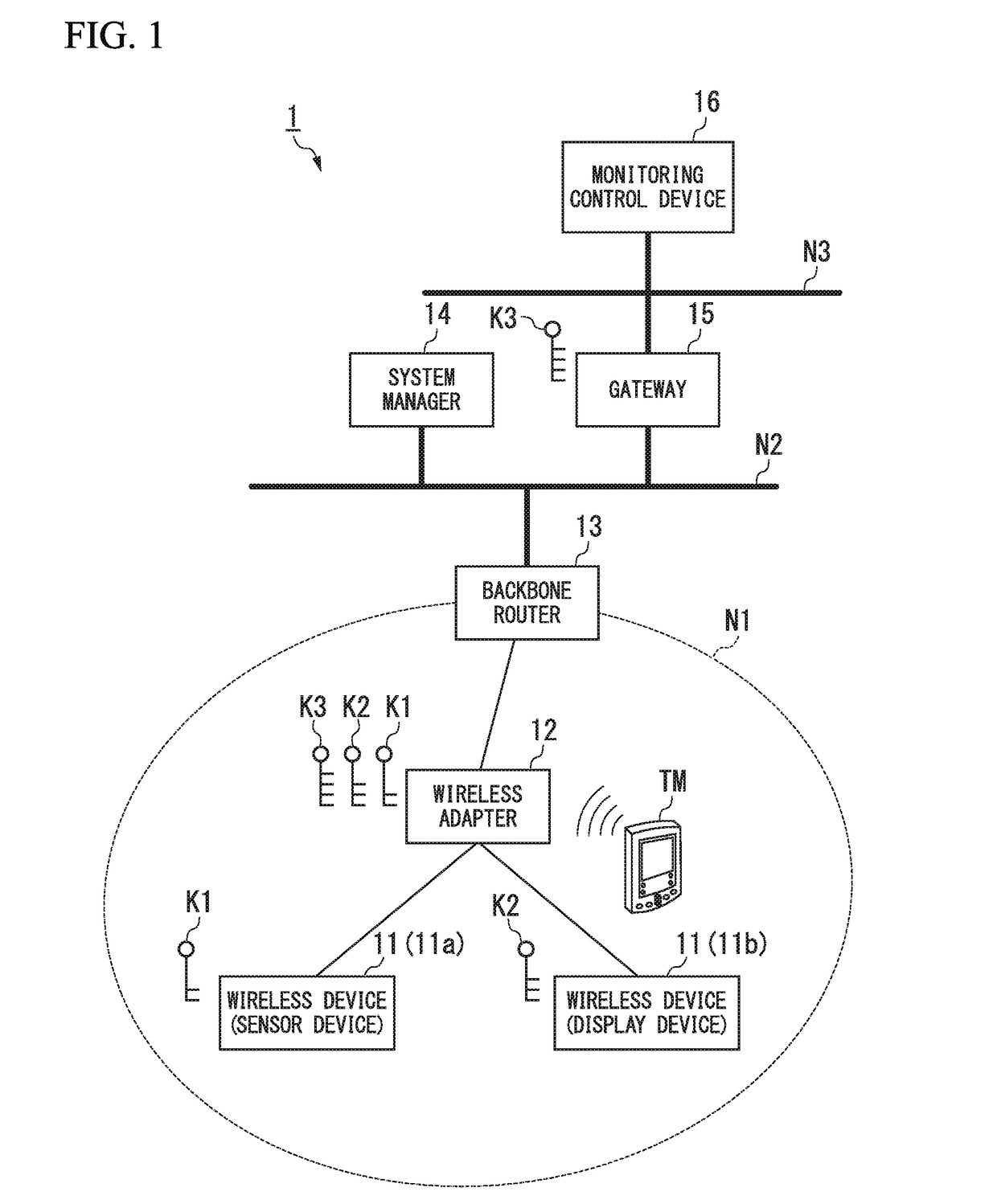
[0046]FIG. 1 is a block diagram showing the overall configuration of a wireless communication system according to the first embodiment of the present invention. As shown in FIG. 1, a wireless communication system 1 according to the present embodiment includes, for example, a wireless device 11, a wireless adapter 12 (wireless relay device), a backbone router 13, a system manager 14, a gateway 15, and a monitoring control device 16. The wireless communication system 1 having this configuration can wireless communication using a TDMA (Time Division Multiple Access) system via a wireless network N1.

[0047]The wireless communication system 1 is constructed in a plant or a factory or the like (hereinafter, collectively referred to simply as a plant). The plant includes, for example, in addition to an industrial plant such as a chemical industrial plant, a plant for managing and controlling a wellhead such as a gas field and oil field and its surroundin...

second embodiment

[0086](Wireless Communication System)

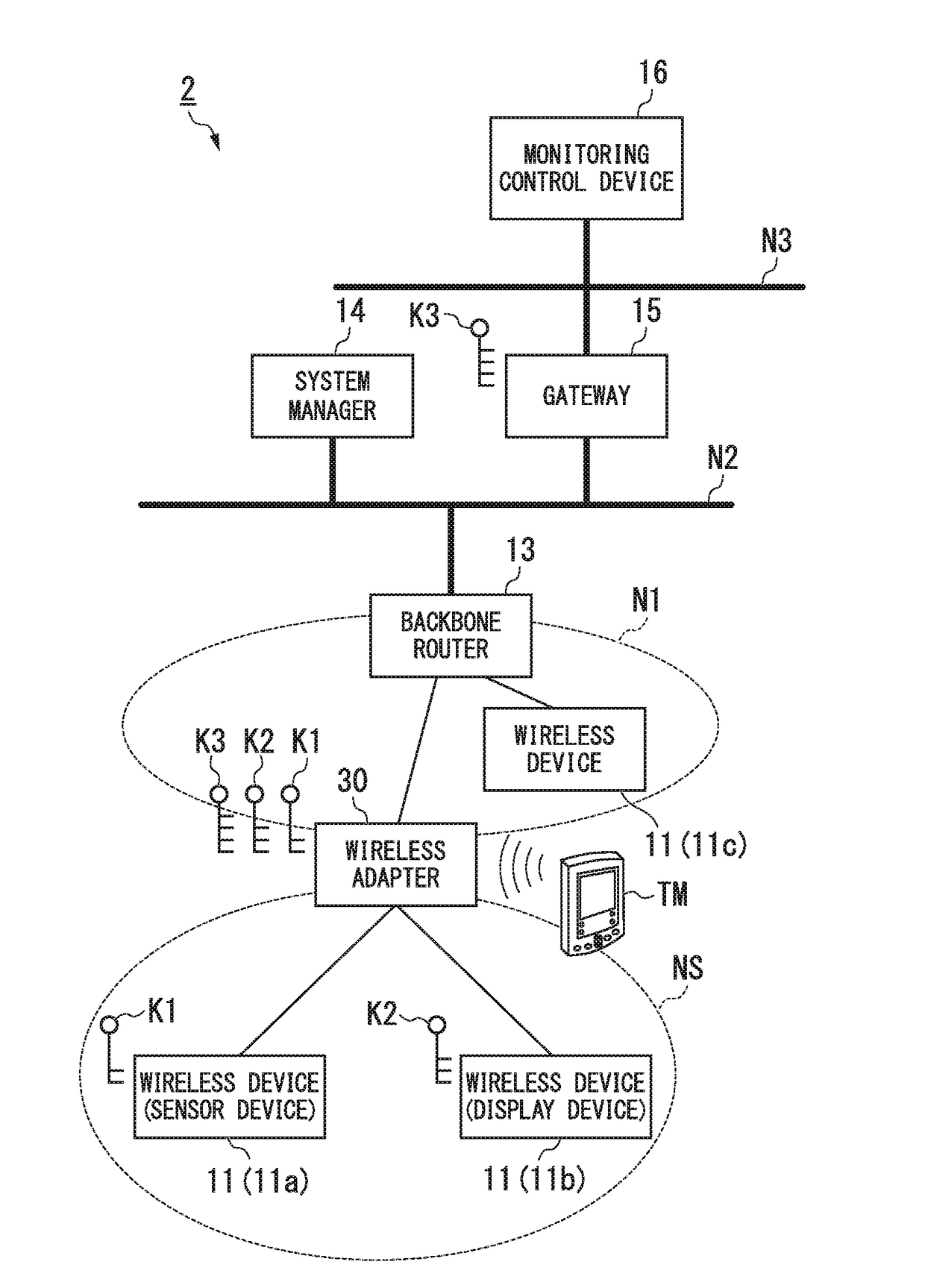
[0087]FIG. 4 is a block diagram showing the overall configuration of a wireless communication system according to the second embodiment of the present invention. In FIG. 4, blocks that correspond to those in FIG. 1 are assigned the same reference numerals, the description will be omitted. As shown in FIG. 4, a wireless communication system 2 according to the present embodiment includes a wireless adapter 30 instead of the wireless adapter 12 in the wireless communication system 1 shown in FIG. 1, and manages, using the wireless adapter 30, a sub wireless network NS (second wireless network) different from the wireless network N1 (first wireless network), in which the wireless adapter 30 joins.

[0088]The reason for performing such a control is that, even if the failure of the system manager 14 occurs and the operation of the wireless network N1 is stopped, the operation of the sub wireless network NS managed by the wireless adapter 30 is continued....


PUM


Abstract

A wireless relay device for relaying encrypted data via a wireless network according to one aspect of the present invention includes a relay controller and an encryption processor. The relay controller is configured to relay a first data to a predetermined relay destination as a second data via the wireless network. The first data is transmitted to the wireless relay device via the wireless network and is addressed to the wireless relay device. The encryption processor is configured to decrypt the first data into a decrypted first data and to input the decrypted first data into the relay controller, and encrypt the second data to be relayed by the relay controller.

Description

BACKGROUND OF THE INVENTION[0001]Field of the Invention[0002]The present invention relates to a wireless relay device, a wireless communication system, and a wireless relay method.[0003]Priority is claimed on Japanese Patent Application No. 2015-073056, filed on Mar. 31, 2015, the contents of which are incorporated herein by reference.[0004]Description of Related Art[0005]In a plant or a factory or the like, a distributed control system (DCS) has been implemented to realize a high level of automated operation. In the distributed control system, on-site devices (measures and actuators), which are referred to as field devices, are connected via a communication means to controllers, which control the field devices. The communication system which forms the base of such a distributed control system had been almost always one that communicates by cable. In recent years, a wireless communication system which communicates wirelessly in conformance with an industrial wireless communication s...

Claims


Application Information

Patent Timeline
Patent Type & Authority Patents(United States)
IPC IPC(8): H04L29/06H04W12/02H04B7/155H04W12/10H04W88/04
CPCH04W12/10H04W12/02H04B7/155H04W88/04G05B19/4185H04L67/12H04W40/22H04W52/0209H04W12/03
Inventor FUJIMOTO, NAOYUKIYAMAJI, MASATOTAKEDA, KENICHISHIOYA, MASAKIFURUKAWA, YOTA
Owner YOKOGAWA ELECTRIC CORP
Why Eureka
Try Eureka