Edge-detecting device and image-forming device provided with the same

a technology of image-forming device and edge-detecting device, which is applied in the direction of printing mechanism, instruments, transportation and packaging, etc., can solve the problems of reducing the accuracy of detecting the edge position of the recording medium, and affecting the accuracy of detecting the edge position

Inactive Publication Date: 2005-09-20
BROTHER KOGYO KK
View PDF24 Cites 41 Cited by
  • Summary
  • Abstract
  • Description
  • Claims
  • Application Information

AI Technical Summary

Benefits of technology

[0006]However, there will be the case that the recording medium is partially soiled or has preprinted images such as logos or pictures. There will be another case that the recording medium has wrinkled areas. If the amount of light emitted by the light-emitting unit is adjusted so that the amount of light received by the light-receiving unit from such a soiled, printed, or wrinkled position on the recording medium will attain the target value, the light-emitting unit is adjusted to emit light of an inappropriate amount. This decreases accuracy for detecting the edge positions of the recording medium.
[0007]In view of the foregoing, it is an object of the present invention to provide an improved edge-detecting device that is capable of accurately detecting the edge positions of a recording medium without being affected by differences in states in respective parts of the recording medium and an improved image-forming device provided with the edge-detecting device.

Problems solved by technology

However, there will be the case that the recording medium is partially soiled or has preprinted images such as logos or pictures.
There will be another case that the recording medium has wrinkled areas.
This decreases accuracy for detecting the edge positions of the recording medium.

Method used


Image

  • Edge-detecting device and image-forming device provided with the same
  • Edge-detecting device and image-forming device provided with the same
  • Edge-detecting device and image-forming device provided with the same

Examples


first embodiment

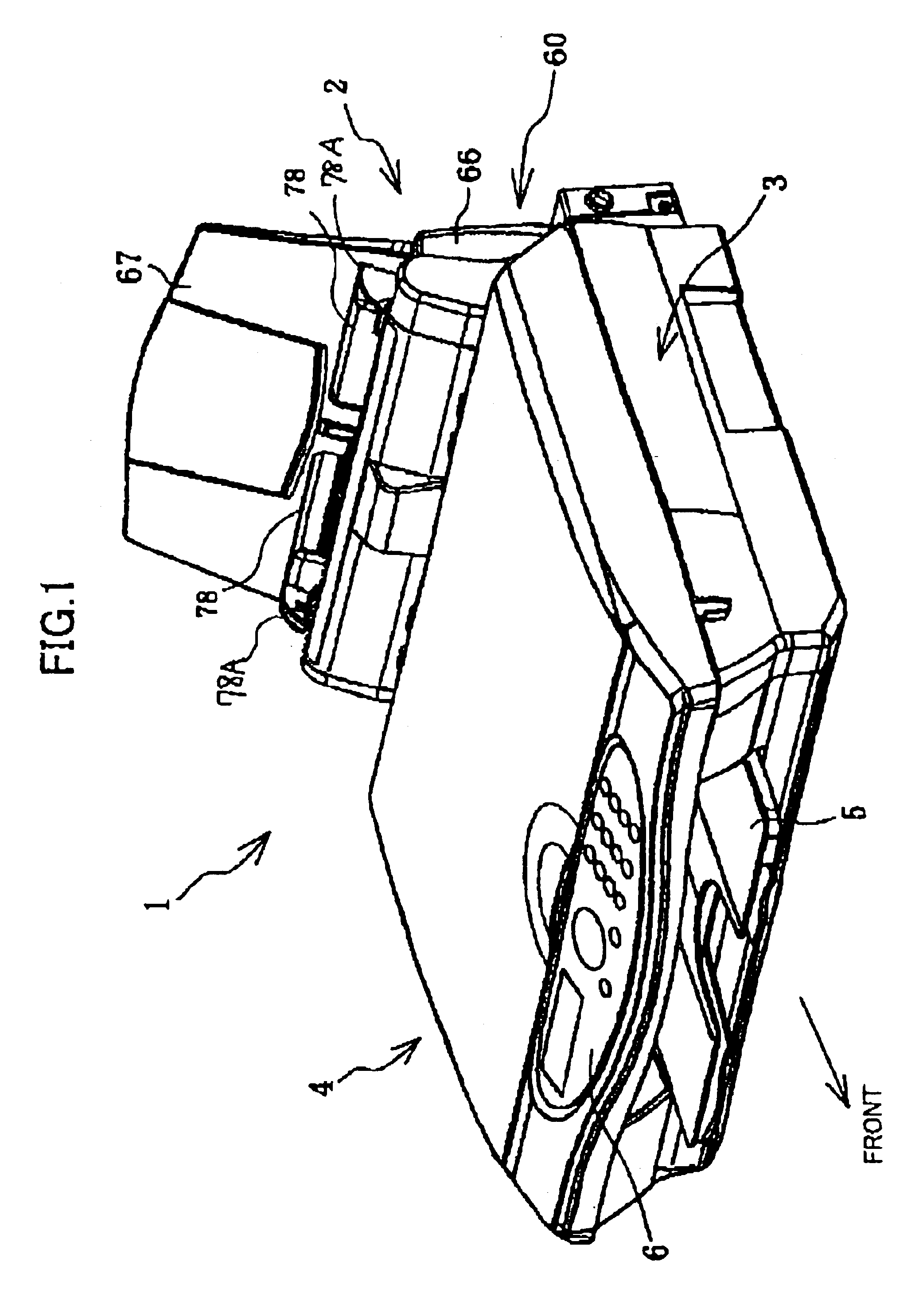
[0031]FIG. 1 is a perspective view of the multifunction device 1 of the present invention.

[0032]As shown in FIG. 1, a paper supplying unit 2 is provided in the rear section of the multifunction device 1. An inkjet printer 3 is provided in front of and below the paper supplying unit 2. A scanning unit 4 for implementing the copier function and facsimile function is provided above the printer 3. A discharge tray 5 is provided on the front side of the printer 3. An operating panel 6 is provided on the top surface on the front end of the scanning unit 4.

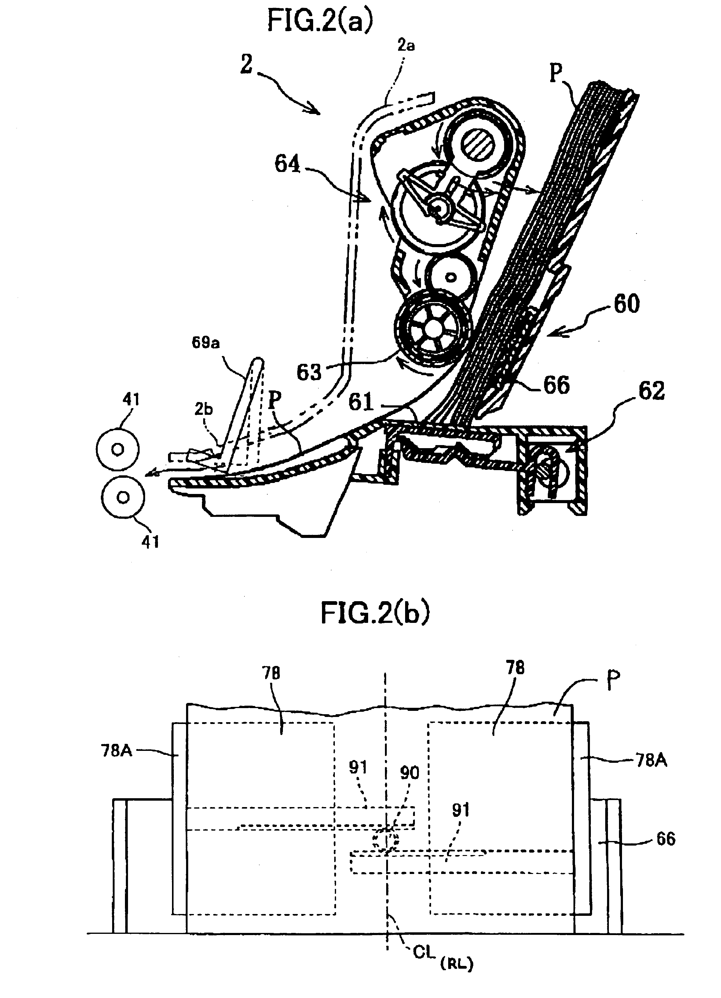
[0033]Next the paper-supplying unit 2 will be described in greater detail. FIG. 2 is a vertical cross-sectional view showing the paper-supplying unit 2 of the multifunction device 1.

[0034]As shown in FIG. 2(a), the paper-supplying unit 2 includes a paper holder 60, a pair of left and right stoppers 61, a stopper position switching mechanism 62, a paper-supplying mechanism 64 having a paper-feeding roller 63, and a paper feed motor 65 (se...

second embodiment

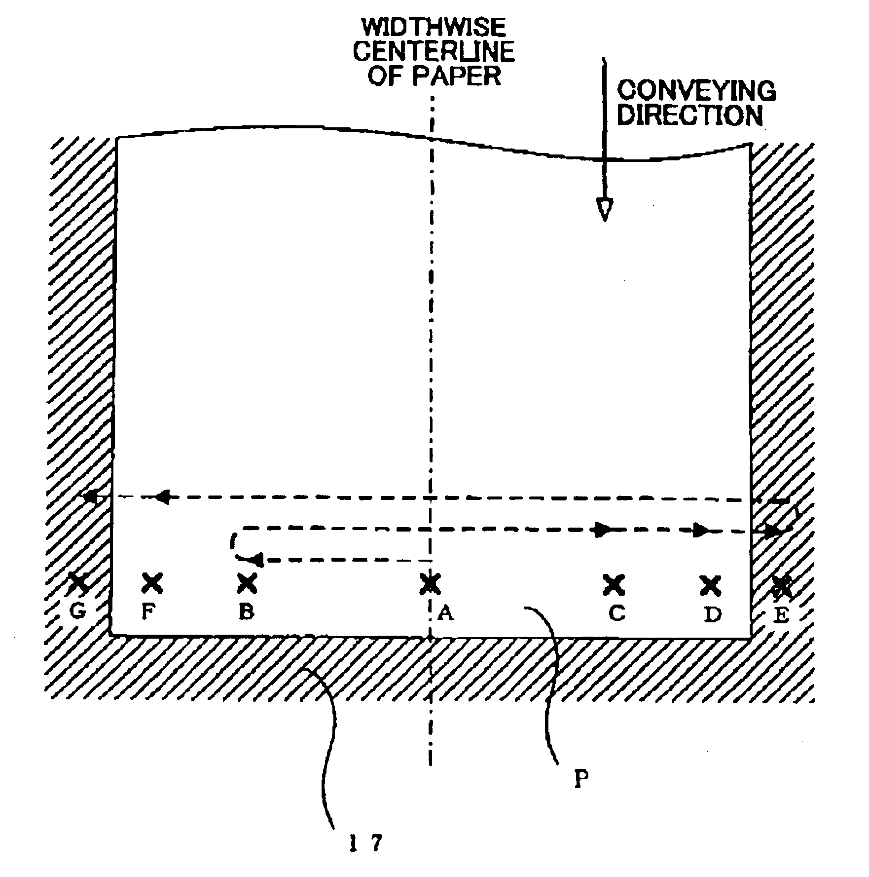
[0158]In the second embodiment, the threshold adjusting process for the light-emitting element 79 is performed at the plurality of locations on the paper P. Specifically, the control unit 70 performs these processes in the pattern shown in FIG. 10, but these processes may be performed in a variety of patterns other than this pattern. For example, these processes may be performed in the patterns shown in FIGS. 15-17.


PUM


Abstract

An image-forming device includes a media sensor having a light-emitting element and a light-receiving element for detecting edge positions of a paper based on values outputted from the light-receiving element as the target detection area of the media sensor is moved in relation to the paper. The value of a current to be supplied to the light-emitting element for edge detection is determined in the following manner. First, the media sensor is moved to the center of the paper-conveying path (S110). Then, the paper is conveyed to a prescribed position (S120-S150). Next, the value of the current that should be supplied to the light-emitting element (light amount adjusting value) in order that output from the light-receiving element will reach a desired value is determined at a position A on the paper at which the target detection area of the media sensor is being presently located (S160, S170). The target detection area is subsequently moved to a position B and a position C, while repeating the process to determine the light amount adjusting value (S180-S230). Finally, the paper edge detecting current is set to the smallest of the light amount adjusting values determined at positions A-C (S240).

Description

BACKGROUND OF THE INVENTION[0001]1. Field of the Invention[0002]The present invention relates to an edge-detecting device and an image-forming device such as a printer provided with the edge-detecting device.[0003]2. Description of Related Art[0004]Conventional image-forming devices such as ink-jet printers that form images on a recording medium while conveying that recording medium detect the edge positions of the recording medium in order to position the images on the recording medium with accuracy.[0005]Japanese unexamined patent application publication No. 2000-109243, for example, discloses an image-forming device including an optical sensor having a light-emitting unit that irradiates light and a light-receiving unit that detects the irradiated light reflected off a recording medium. This image-forming device determines the existence of a recording medium based on whether the detection value of the optical sensor is greater than a threshold value. The image-forming device dete...

Claims


Application Information

Patent Timeline
Patent Type & Authority Patents(United States)
IPC IPC(8): B41J11/00B41J2/01B41J11/42B41J29/38B65H7/14
CPCB41J11/008B41J11/0095
Inventor SATO, TATSUYA
Owner BROTHER KOGYO KK
Why Eureka
Try Eureka