Ankle-foot orthosis

an ankle and orthotic technology, applied in the field of orthotics, can solve the problems of inability to clear the toe, excessive plantar flexion, inability to control the falling of the foot, etc., and achieve the effect of variable stiffness properties

Active Publication Date: 2005-09-20
KAUPTHING BANK
View PDF28 Cites 102 Cited by
  • Summary
  • Abstract
  • Description
  • Claims
  • Application Information

AI Technical Summary

Benefits of technology

[0021]The foot plate may have a curvilinear shape and variable stiffness properties between the heel and toe ends. The design of the foot plate in the present invention provides a smooth toe rollover or transition of compressive forces from a heel-strike position to a toe-off position thereby providing a natural feeling during a walking stride while a patient wears the orthosis. In areas of the orthosis that are subject to higher degrees of stress relative to other areas, such areas are reinforced with additional reinforcing fibers.
[0022]Unlike the aforementioned orthotic devices of the prior art...

Problems solved by technology

First, the individual cannot control the falling of their foot after striking their heel.
Impairment of the dorsiflexor muscles thus results in excessive plantar flexion which is the action of extending the foot from a position substantially perpendicular to the lower leg to a position substantially parallel to the lower leg.
The second complication is the inability to clear the toe during the swing phase of a gait cycle.
This causes the person to drag their toe on the ground throughout the swing phase.
Furthermore, due to impairment of the anterior tibialis, in particular at the medial arch of the foot, the ankle is typically everted and pronated.
This ankle-foot orthosis is disadvantageous in that the orthosis extends along the dorsal portion of the leg and affects the joints unfavorably to produce a very stiff gait.
Another disadvantage to this orthosis is that the calf and Achilles tendon are subjected to heavy stresses which may cause pain and discomfort to the patient wearing the orthosis.
Yet further, this orthosis has an undesirable effect on a patient's leg during a gait cycle since the orthosis is solely positioned on the back of the heel and therefore does not provide a smooth heel strike.
Contrariwise, a disadvantage to this orthosis is that it permits a significant degree of plantar flexion since it lacks proper anterior support and only reinforces the posterior of the ankle and foot.
Moreover, this design does not provide any lateral support, and therefore, unless people wear high and strong shoes, inversion of the foot is not prevented.
In practice, it has been found that the anterior shell covering the lower leg can cause a patient discomfort due to the amount of area covered along t...

Method used


Image

  • Ankle-foot orthosis
  • Ankle-foot orthosis
  • Ankle-foot orthosis

Examples


Embodiment Construction

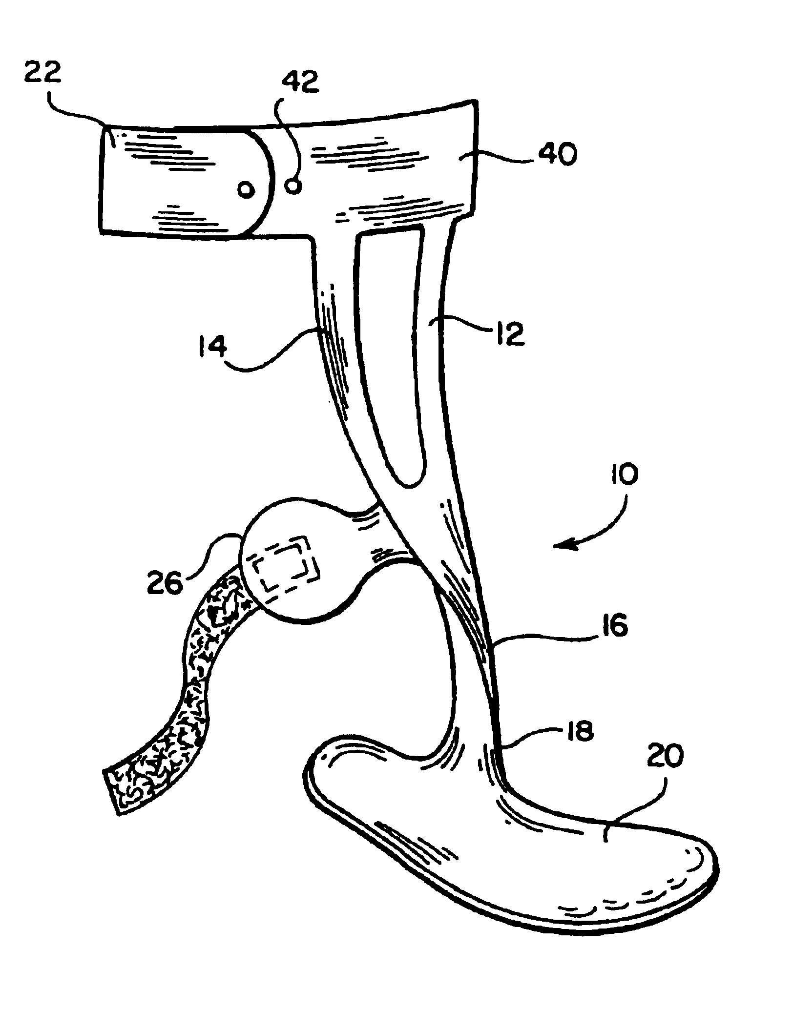
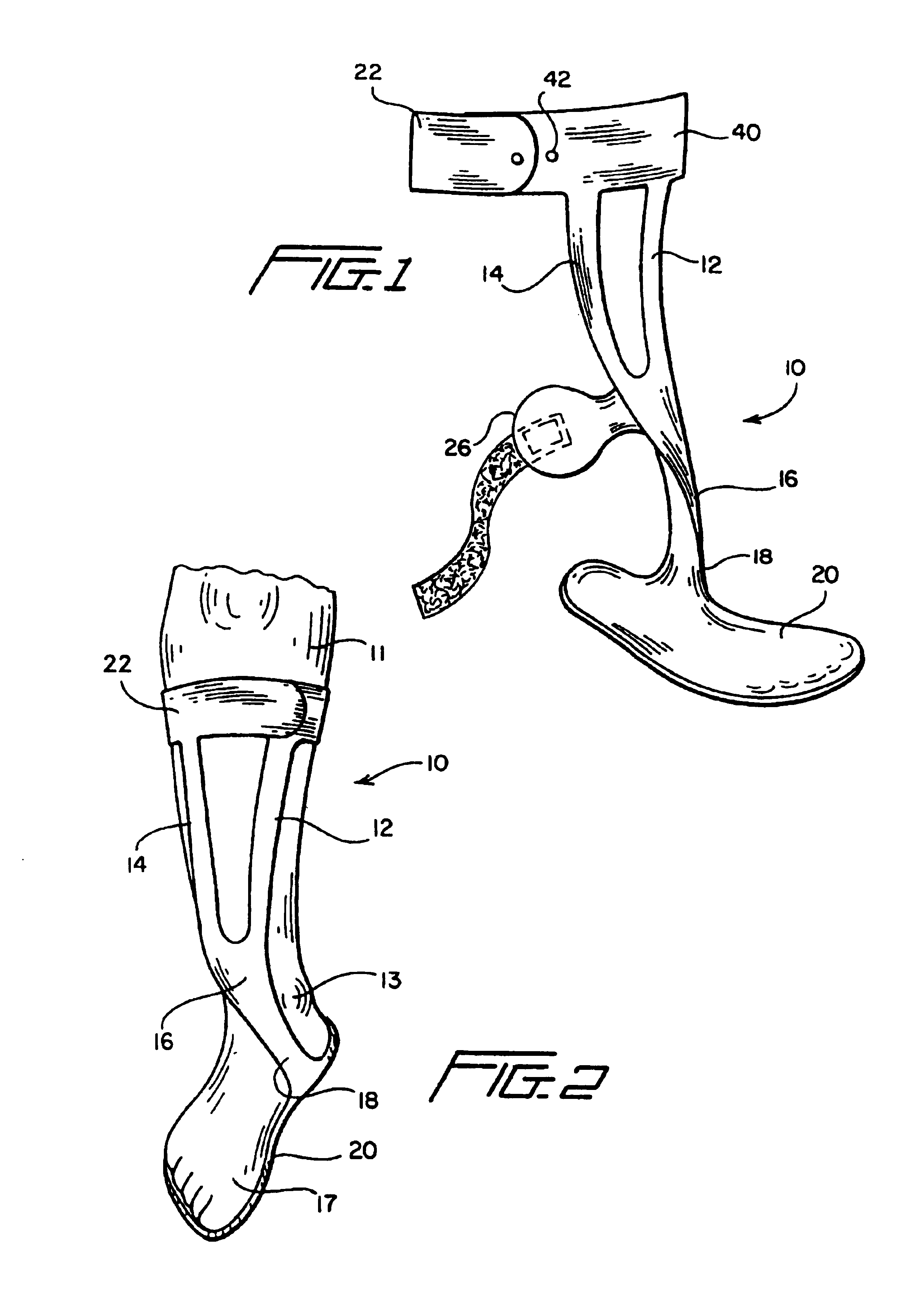
[0037]With reference to FIGS. 1 and 2, a preferred embodiment of the ankle-foot orthosis of the present invention is shown. The ankle-foot orthosis generally comprises a monolithic frame 10 including at least one layer of fabric impregnated with a hardened structural resin. In this embodiment, the orthosis includes lateral and medial anterior support members 12, 14, respectively, configured and dimensioned to extend downwardly from below a knee of a patient's leg 11 along the anterior of the leg 11 thereby defining a clearance therebetween along a portion of the length of the leg 11. The lateral and medial anterior support members 12, 14 join in advance of a patient's ankle joint 13 to define an anterior ankle portion 16. The ankle portion 16 preferably extends to a medial connection 18 extending around the medial side of a patient's ankle 13 and connecting to a foot plate 20 located beneath the sole of a patient's foot 17.

[0038]Alternatively, the ankle portion may extend to a later...


PUM


Abstract

An ankle-foot orthosis having a structural frame formed from at least one layer of fabric impregnated with a hardened structural resin. The frame includes at least one anterior support member that extends downwardly from an upper leg engaging portion to define an anterior ankle portion which extends to a medial portion connected to a foot plate.

Description

[0001]This application claims the benefit of U.S. Provisional Application No. 60 / 424,321, filed Nov. 7, 2002.BACKGROUND OF THE INVENTION[0002]1. Field of the Invention[0003]The present invention relates to orthotic devices utilized to limit the movement of a lower limb. More particularly, the present invention relates to an ankle-foot orthosis for stabilizing and controlling motion of the ankle and foot.[0004]2. Description of the Related Art[0005]An ankle-foot orthosis is a medical device used to support and align the ankle and foot by suppressing spastic and overpowering ankle and foot muscles, assisting weak and paralyzed muscles of the ankle and foot, and preventing or correcting ankle and foot deformities.[0006]An ankle-foot orthosis is particularly useful in assisting the functions of the ankle and foot when a person has a gait condition commonly known as “drop foot.” Drop foot is a neuro-muscular condition resulting in the inability of a person to sufficiently lift one of the...

Claims


Application Information

Patent Timeline
IPC IPC(8): A61F5/00A61F5/37A61FA61F5/01A61F13/00
CPCA61F5/0113
Inventor INGIMUNDARSON, ARNI THOROLAFSSON, ORNCLAUSEN, ARINBJORN VIGGODE ROY, KIM PETER VIVIANE
Owner KAUPTHING BANK
Why Eureka
Try Eureka