Communication terminal and channel connection

Inactive Publication Date: 2005-09-20
FUJITSU TOSHIBA MOBILE COMM LTD
View PDF19 Cites 6 Cited by
  • Summary
  • Abstract
  • Description
  • Claims
  • Application Information

AI Technical Summary

Benefits of technology

[0011]The present invention hence has an object of providing a communication terminal and a channel connection method by which information of a radio

Problems solved by technology

Therefore, when a response is made to a communication request from a calling party, there is a drawback that the communication channel to this calling party cannot be transferred to another communication terminal.
That is, the calling party mu

Method used


Image

  • Communication terminal and channel connection
  • Communication terminal and channel connection
  • Communication terminal and channel connection

Examples


Embodiment Construction

[0031]In the following, an embodiment of the present invention will be explained with reference to the drawings.

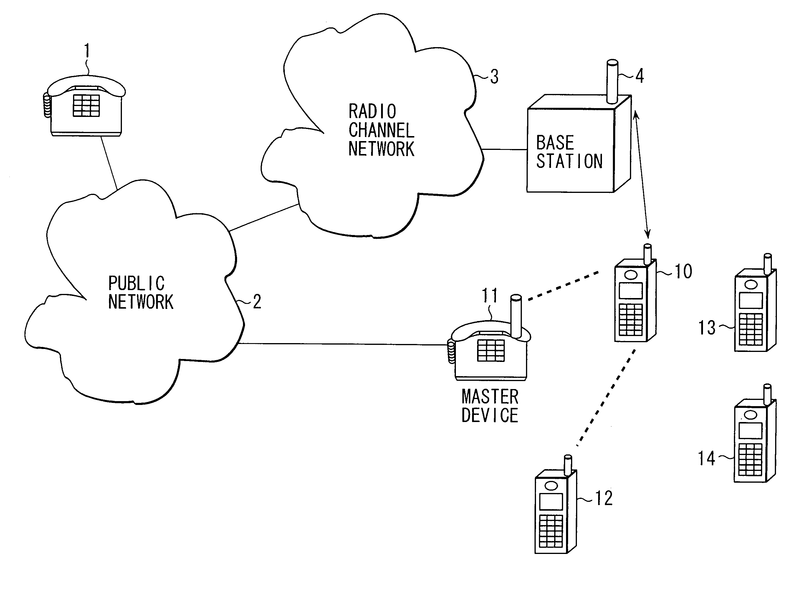
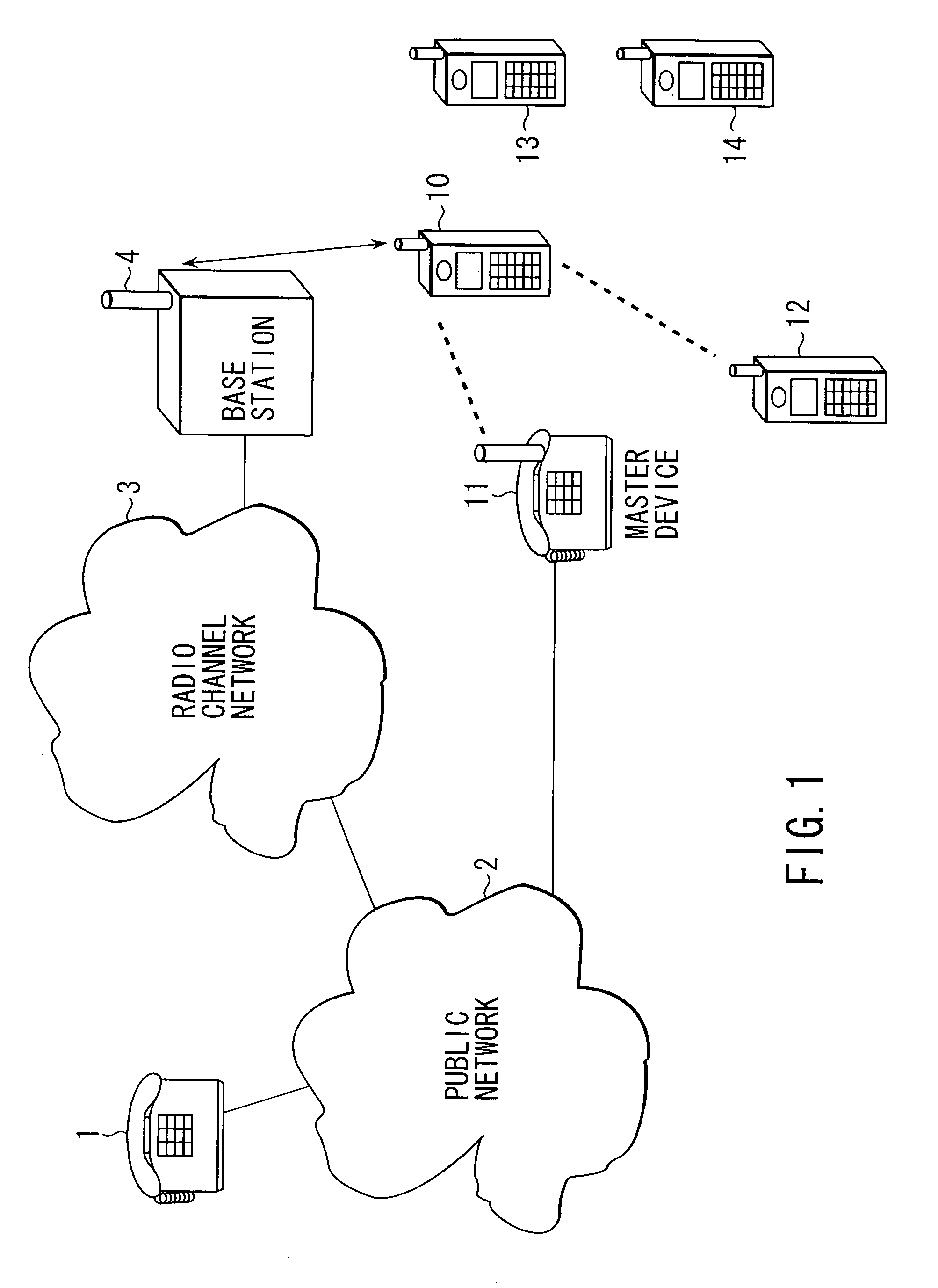
[0032]FIG. 1 is a view showing a channel connection form using a communication terminal according to the present invention. The reference symbol 1 in the figure denotes a communication terminal in the opposite side. The reference symbols 2, 3, 4, and 10 respectively denote a public network, a radio channel network, a base station, and a communication terminal of the present invention.

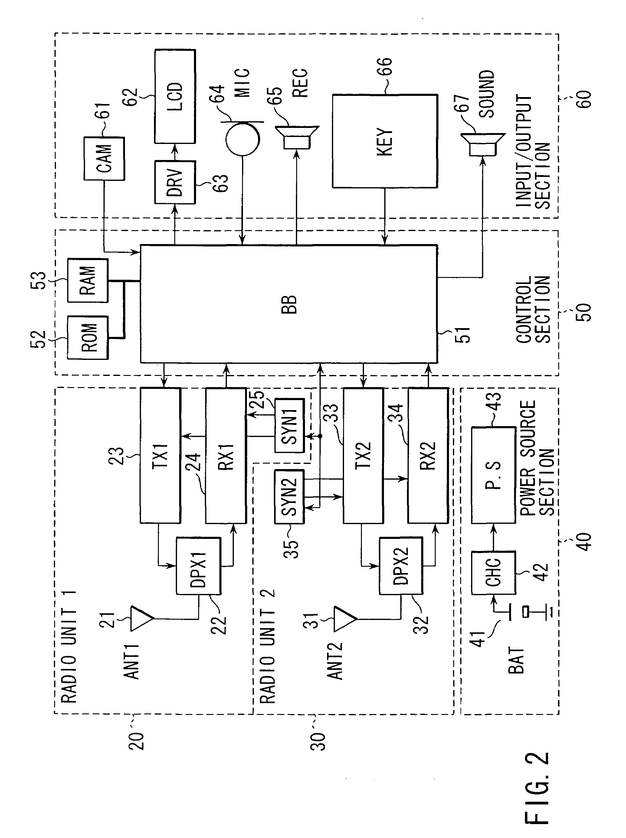
[0033]The communication terminal 10 is established by, for example, a mobile communication terminal device such as a portable phone, a PHS, or the like. This communication terminal comprises at least a first radio unit and a second radio unit. The first radio unit makes radio communication with the base station 4, using a radio wave of a predetermined radio frequency band. The second radio unit makes communication with one of other communication terminals 12 to 14 or a master device 11 connect...


PUM


Abstract

The communication terminal comprises a first radio unit for making radio communication with a base station over a first radio channel having a first radio frequency band, and a second radio unit for making radio communication with another communication terminal by using a second radio channel having a second radio frequency band. A first channel establishing section establishes the first radio channel to the base station through the first radio unit. A second channel establishing section establishes the second radio channel to the another communication terminal through the second radio unit. A control section connects the base station to the another communication terminal over the first and second radio channels.

Description

CROSS-REFERENCE TO RELATED APPLICATIONS[0001]This application is based upon and claims the benefit of priority from the prior Japanese Patent Application No. 11-280042, filed Sep. 30, 1999, the entire contents of which are incorporated herein by reference.BACKGROUND OF THE INVENTION[0002]The present invention relates to a mobile communication terminal such as a portable phone, a PHS (Personal Handy Phone), or the like, and a channel connection method therefore.[0003]Conventionally, an analogue or digital portable phone is a kind of terminal that forms a radio channel. Communication is made with a calling party in the opposite, which is connected to a public telephone network, through a base station connected to a radio channel network.[0004]This state is shown in FIG. 8. This figure shows a conventional channel connection form. In this figure, the reference symbol 1 denotes a communication terminal of a communication in the opposite side. The reference symbols 2, 3, 4, and 5 respect...

Claims


Application Information

Patent Timeline
IPC IPC(8): H04M1/725H04M1/72H04M1/733H04Q7/32H04Q7/38H04M1/00H04M1/72505H04M1/72513H04W4/16H04W76/04H04W88/04H04W88/06
CPCH04M1/72505H04M1/72513H04M1/733H04W76/022H04M2250/02H04W4/16H04W88/04H04W88/06H04W76/12
Inventor YAMAGUCHI, KENTOKUITO, KOICHI
Owner FUJITSU TOSHIBA MOBILE COMM LTD
Why Eureka
Try Eureka