Method of modifying stamping tools for spring back compensation based on tryout measurements

a technology of spring back compensation and stamping tool, which is applied in the direction of manufacturing tools, shaping tools, instruments, etc., can solve the problems of large expense, large time expenditure, and large amount of time required for bringing forth satisfactory results

Inactive Publication Date: 2005-09-20
FORD GLOBAL TECH LLC
View PDF4 Cites 25 Cited by
  • Summary
  • Abstract
  • Description
  • Claims
  • Application Information

AI Technical Summary

Benefits of technology

[0011]The above-noted and other advantages of the present invention will become more apparent to those skilled ...

Problems solved by technology

Often the above-noted process of trial and error caused a major expense due to design and redesign of dies.
The prior trial and error method also required significant expenditures of time.
Many of the prior mathematical computational methods of designing dies which could accommodate for spring back require the utilization of computers with a larger amount of power and also require extensive amounts of time to bring forth satisfactory results.
Another problem with many prior predictive techniques is that they fail to converge in some circumstances, such as in case of complex tooling geometries or in case of different...

Method used


Image

  • Method of modifying stamping tools for spring back compensation based on tryout measurements
  • Method of modifying stamping tools for spring back compensation based on tryout measurements
  • Method of modifying stamping tools for spring back compensation based on tryout measurements

Examples


Embodiment Construction

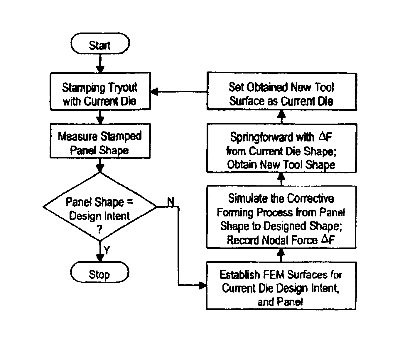
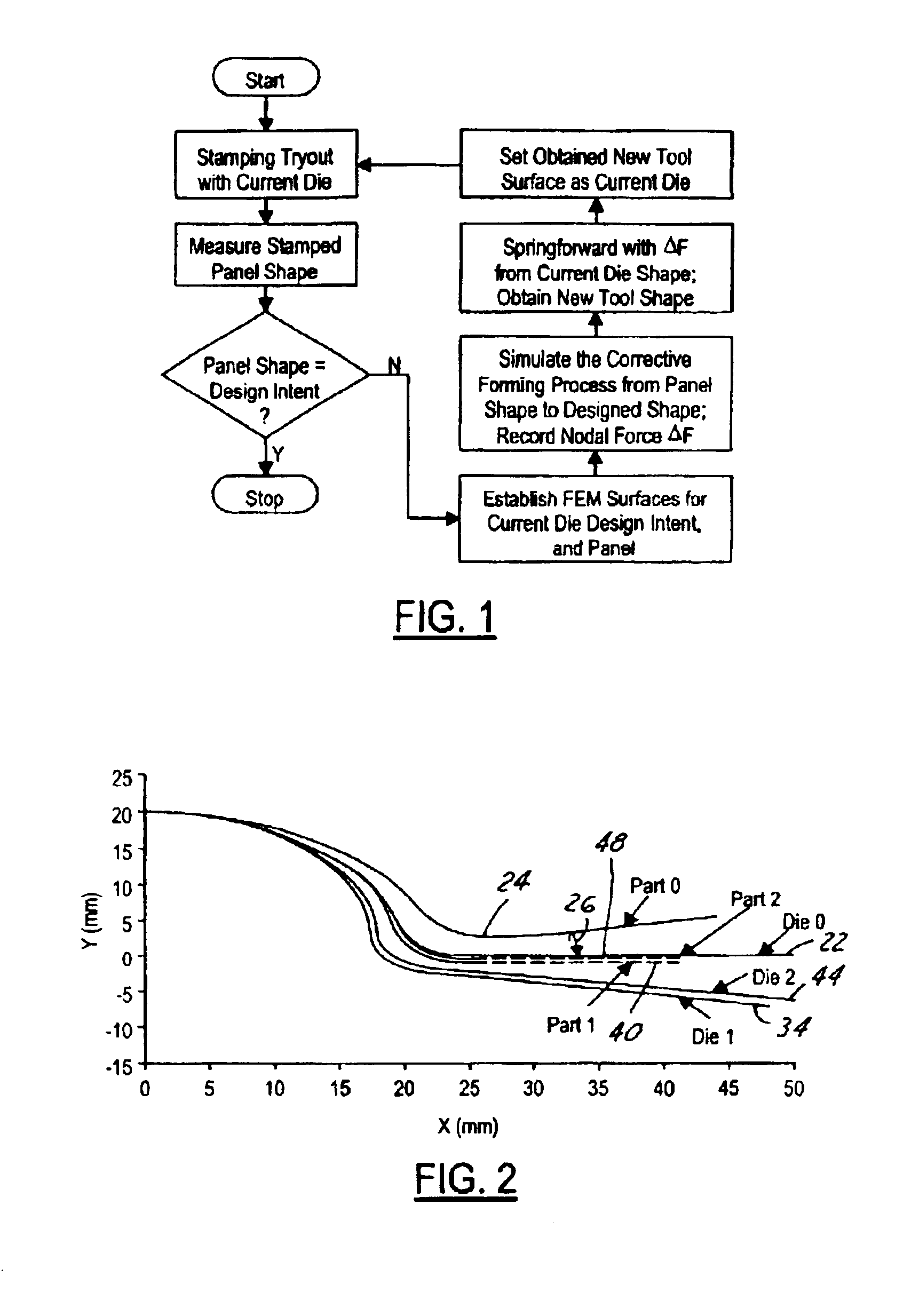
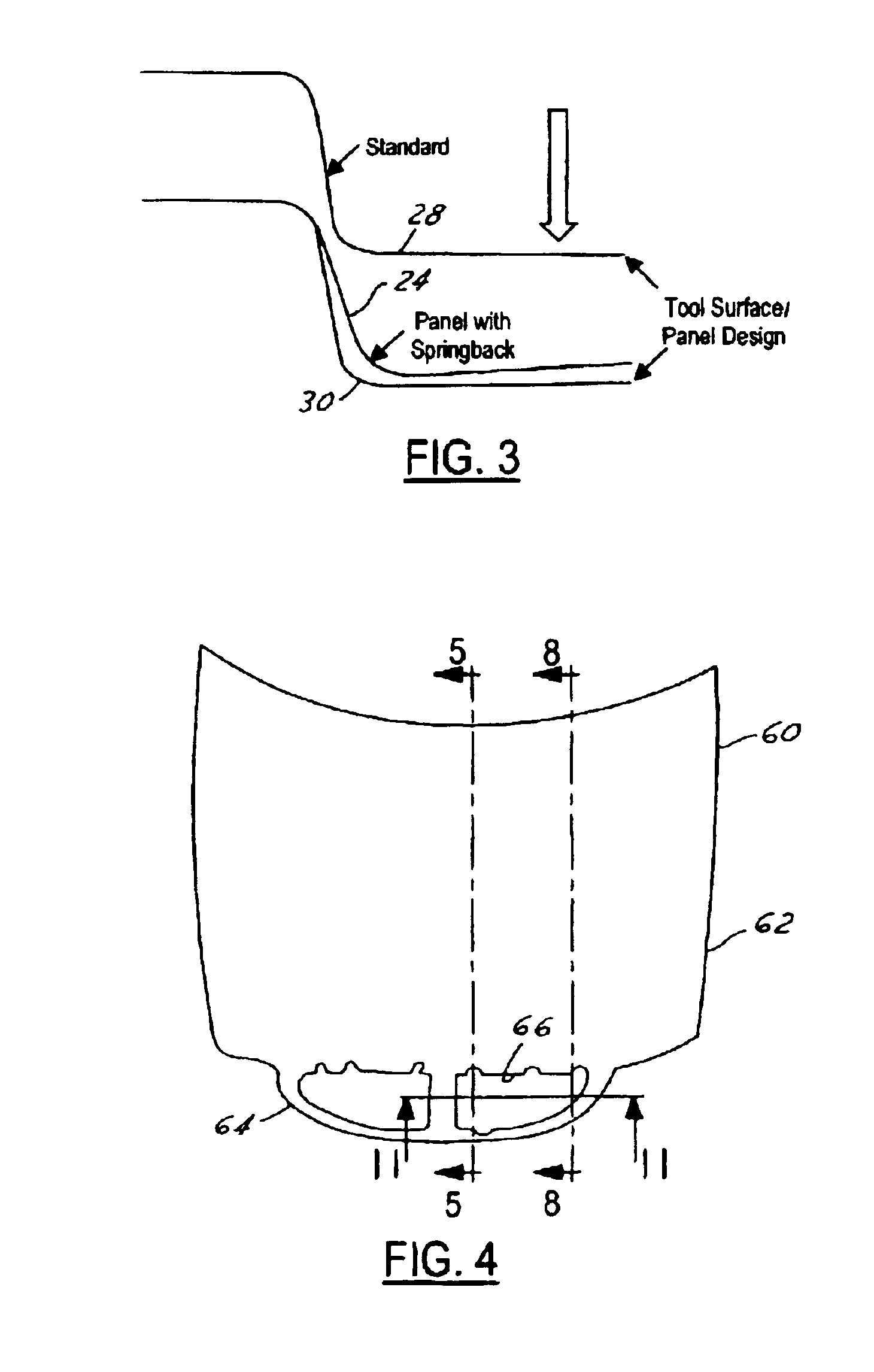
[0025]Referring to FIGS. 1-3, a part having a profile is shown by the line 22 (Die 0). Line 22 denotes a sectional line taken through a three-dimensional part. In the start of the process, a stamping tryout is made using a test or current die. The workpiece will typically start out as a flat sheet of material. The panel or current die, also referred to Die 0, can have a profile that is identical to the profile of the design intent workpiece or may have a profile which has some initial modifications. After stamping, the workpiece is removed from the die. The workpiece initially has a profile shown by line 24 (Part 0). This profile will be measured by appropriate means including but not limited to optical scanning techniques. Another technique is to use a coordinate measuring machine. A coordinate measurement machine has a needle-type contact point which travels along the surface to measure its geometry. Between the lines 22 and 24 is a spring back, FIG. 2, item 26.

[0026]A comparison ...


PUM

PropertyMeasurementUnit
Forceaaaaaaaaaa
Surfaceaaaaaaaaaa

Abstract

A method of developing a stamping die for a workpiece is provided, which includes the steps of stamping a workpiece in a current die. A measurement is made of the stamped workpiece to determine its profile. The profile is compared with the design intent workpiece to determine dimensional variance. If the variance is within predetermined limits, the development is complete. If the variance is beyond limits, a conceptual determination is made of the residual forces in the current die stamped workpiece when the current die stamped workpiece is restamped by a design intent die. This conceptual determination is carried out on a computer. From the determination of residual forces, a new current die is developed. The new current die then stamps the workpiece. The steps are repeated until the stamped workpiece profile is within predetermined limits.

Description

BACKGROUND OF INVENTION[0001]1. Field of the Invention[0002]The field of the present invention is designing dies for stamping sheet metal parts. More particularly the present invention relates to designing dies for stamping sheet metal parts which compensate for the tendency of sheet metal parts to spring back after a stamping operation, so that the part process from the die will more exactly match a design intent profile of a part.[0003]2. Background of the Invention[0004]Most automotive vehicles have a plurality of metal stampings which are utilized both in the chassis and automotive vehicle body. In many instances the stamping workpiece starts out as a thin sheet of metal. The metal is pressed between two dies which form the workpiece in the desired configuration. After the stamping operation, the workpiece is trimmed and delivered to another workstation for further metal working operations or assembly with the vehicle. The stamping operation forms the workpiece by plastic deform...

Claims


Application Information

Patent Timeline
IPC IPC(8): G06F19/00B21D22/02B21D37/20
CPCB21D22/02B21D37/20
Inventor REN, FENGXIA, ZHIYONG CEDRIC
Owner FORD GLOBAL TECH LLC
Why Eureka
Try Eureka