Telescoping roof rack assembly for a vehicle having a truck bed

a truck bed and telescopic technology, applied in the field of vehicles, can solve the problem that the assembly still occupies a substantial portion of the vehicle body

a truck bed and telescopic technology, applied in the field of vehicles, can solve the problem that the assembly still occupies a substantial portion of the vehicle body

US20050023314A1Inactive Publication Date: 2005-02-03FORD MOTOR CO

Image

  • Telescoping roof rack assembly for a vehicle having a truck bed
  • Telescoping roof rack assembly for a vehicle having a truck bed
  • Telescoping roof rack assembly for a vehicle having a truck bed

Examples


Embodiment Construction

[0028] In the following figures, the same reference numerals are used to identify the same components in the various views.

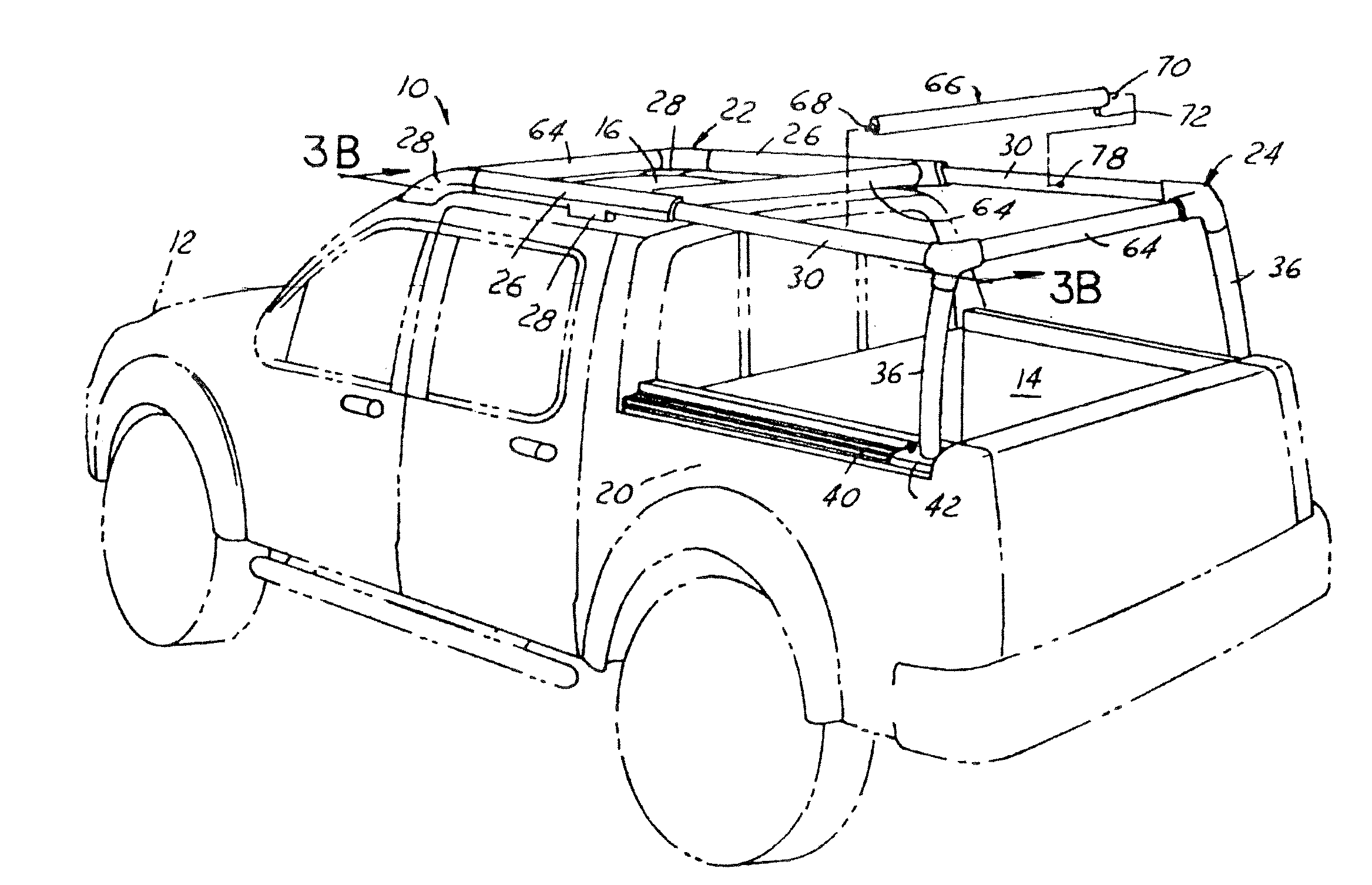
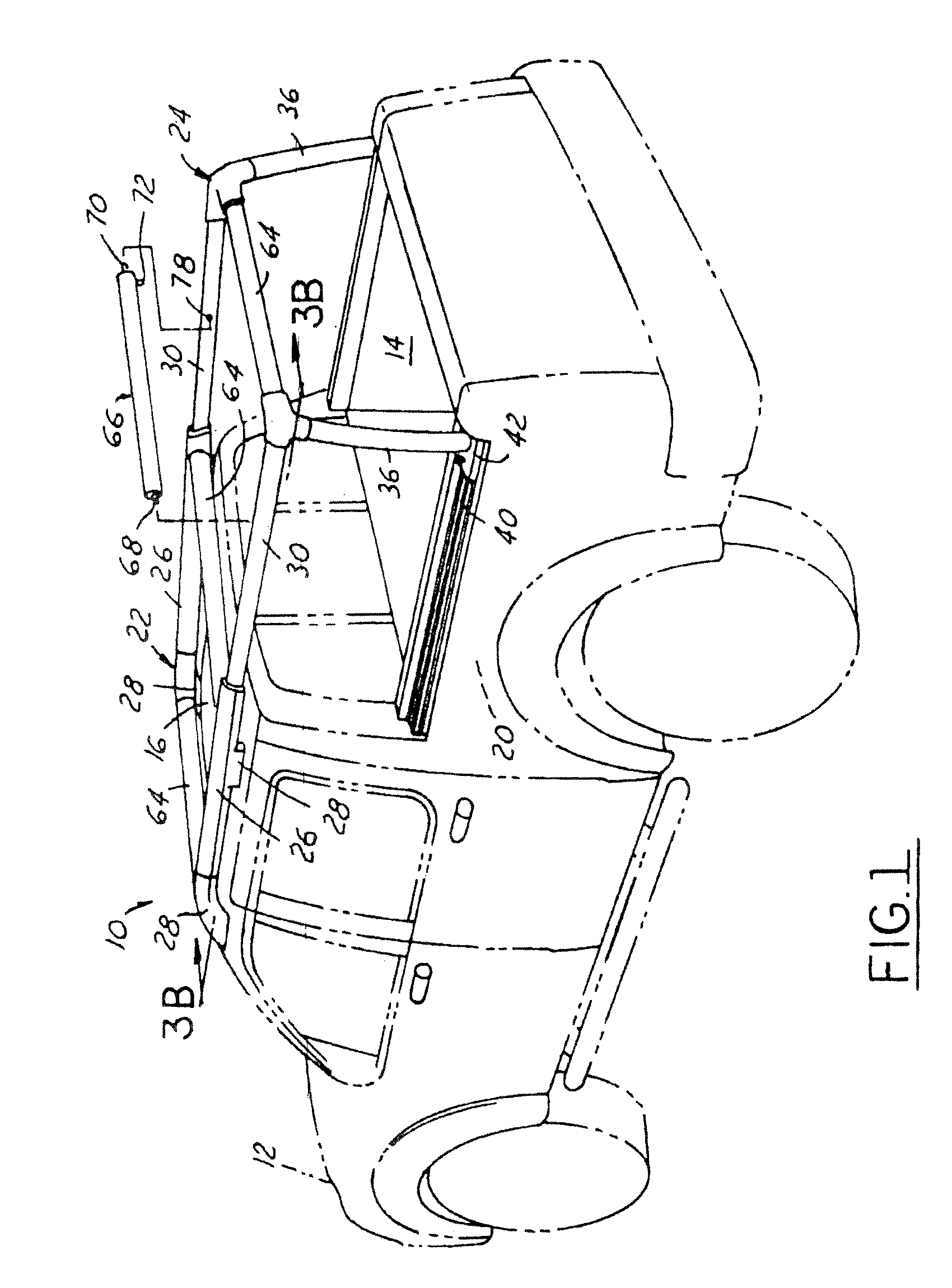
[0029] Referring to FIG. 1, there is shown a perspective view of a telescoping roof rack assembly (hereinafter referred to as “rack assembly”) 10 in a fully extended position and attached to a vehicle 12 having a truck bed 14, in accordance with one embodiment of the present invention.

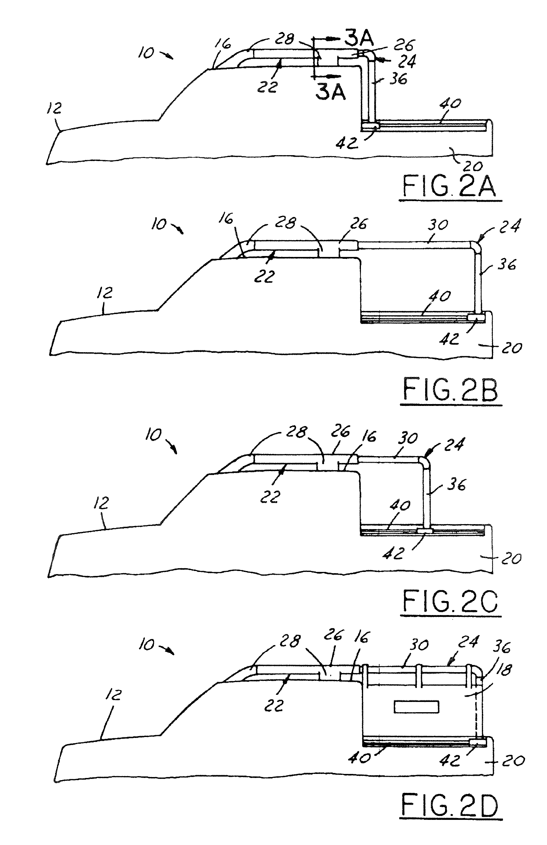
[0030] The rack assembly 10 is moveable between a fully retracted position (as shown in FIG. 2A) and a fully extended position (as shown in FIG. 2B).

[0031] Referring specifically to FIG. 2A, in the fully retracted position, the rack assembly 10 permits unobstructed use of the truck bed 14 such that objects of various shapes and sizes may be placed therein. In other words, when the rack assembly 10 is fully retracted, no part of the rack assembly 10 surrounds the truck bed 14 in a manner that can substantially impair the use of the space within, above, and around the truck bed 14...


PUM


Abstract

A telescoping roof rack assembly (10) for attachment to a vehicle (12) having a truck bed (14) is provided. The rack assembly (10) includes a roof rack section (22) and a truck bed section (24). The roof rack section (22) includes a first pair of supports (26) that are fixedly attached to a roof (16) of the vehicle (12). These supports (26) are positioned substantially parallel to each other and generally along a longitudinal axis of the vehicle (12). The truck bed section (24) includes a second pair of supports (30) that are telescopically coupled to the first pair of supports (26) of the roof rack section (22). Additionally, the second pair of supports (30) have a pair of pillar members (36) extending substantially downward therefrom for slidably coupling to the sidewalls (20) that define the truck bed (14). The rack assembly (10) is moveable between a retracted position and a fully extended position.

Description

BACKGROUND OF INVENTION [0001] The present invention relates generally to vehicles, and more particularly to rack assemblies for vehicles having truck beds. [0002] Rack assemblies for securing various objects within the truck beds of vehicles are well known. Typically, these rack assemblies are aftermarket accessories that are attached to the vehicle for the purpose of transporting relatively large objects. Examples of these large objects can include lengthy ladders, panes of glass, furniture, bikes, canoes, or a variety of other objects. [0003] An adjustable rack assembly for accommodating objects of different lengths is disclosed in U.S. Pat. No. 5,192,107. The “107 patent discloses a multi-sectioned frame assembly having a front section and a rear section. Each section comprises a pair of opposing frame units extending substantially upward from the sidewalls of the truck bed, as well as a plurality of cross members connecting the opposing frame units. The front section is fixedly...

Claims


Application Information

Patent Timeline
03 Feb 2005
Publication
US20050023314A1
IPC
B60P3/40; B60R9/00
CPC
B60R9/00; B60P3/40
Inventors
WILLIAMS, BRUCE PRESTON; KLIMISCH, ERIK