
Ratchet wrench having positioning effect

Active Publication Date: 2005-09-27
LI YI MIN
View PDF1 Cites 58 Cited by
  • Summary
  • Abstract
  • Description
  • Claims
  • Application Information

AI Technical Summary

Benefits of technology

[0005]The present invention is to mitigate and / or obviate the disadvantage of the conventional ratchet wrench.
[0006]The primary objective of the present invention is to provide a ratchet wrench having a rigid positioning effect.
[0007]Another objective of the present invention is to provide a ratchet wrench, wherein the locking portion of the locking plate is extended into the through hole of the cover and detachably locked in the annular groove of the socket to lock the socket on the cover, so that the socket is positioned on the wrench body rigidly and stably without detachment, thereby facilitating a user operating the wrench body and the socket to rotate a workpiece, such as a nut, bolt or the like.
[0008]A further objective of the present invention is to provide a ratchet wrench, wherein the socket is positioned on and detached from the wrench body easily and conveniently by action of the positioning device, thereby facilitating the user operating the ratchet wrench.

Problems solved by technology

However, the socket is not combined with the ratchet wheel rigidly and stably, so that the socket is easily detached from the ratchet wheel during operation, thereby causing inconvenience to a user when operating the wrench body and the socket to rotate the workpiece.

Method used


Image

  • Ratchet wrench having positioning effect
  • Ratchet wrench having positioning effect
  • Ratchet wrench having positioning effect

Examples


Embodiment Construction

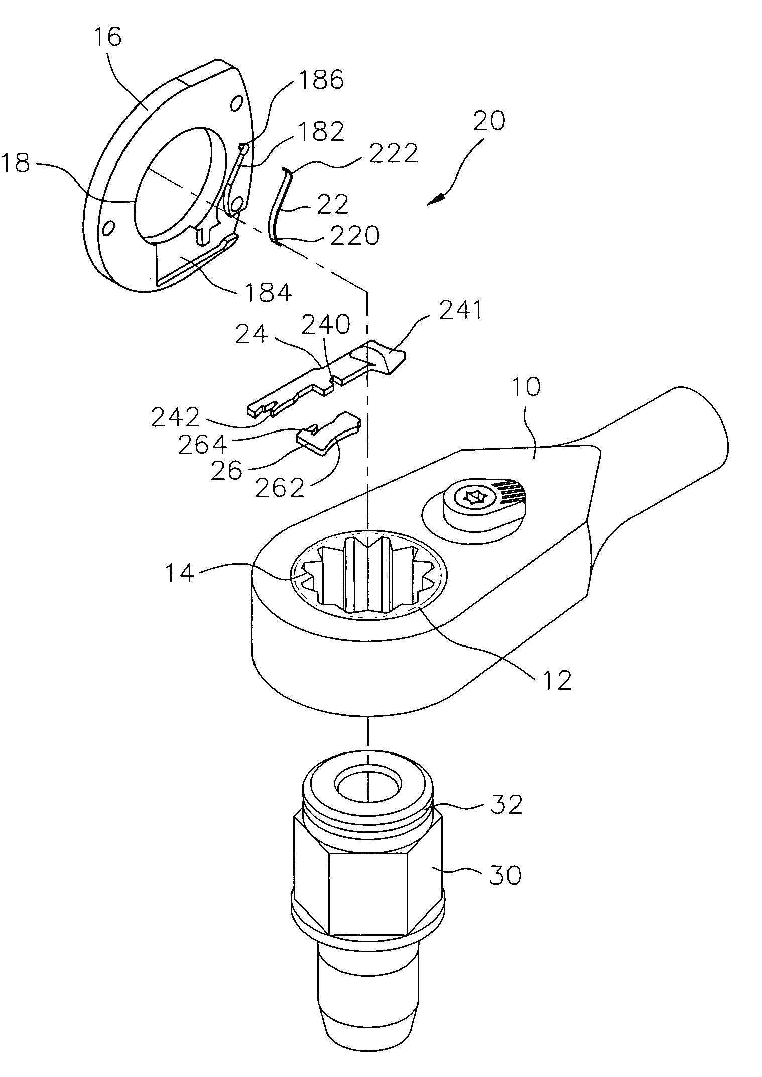
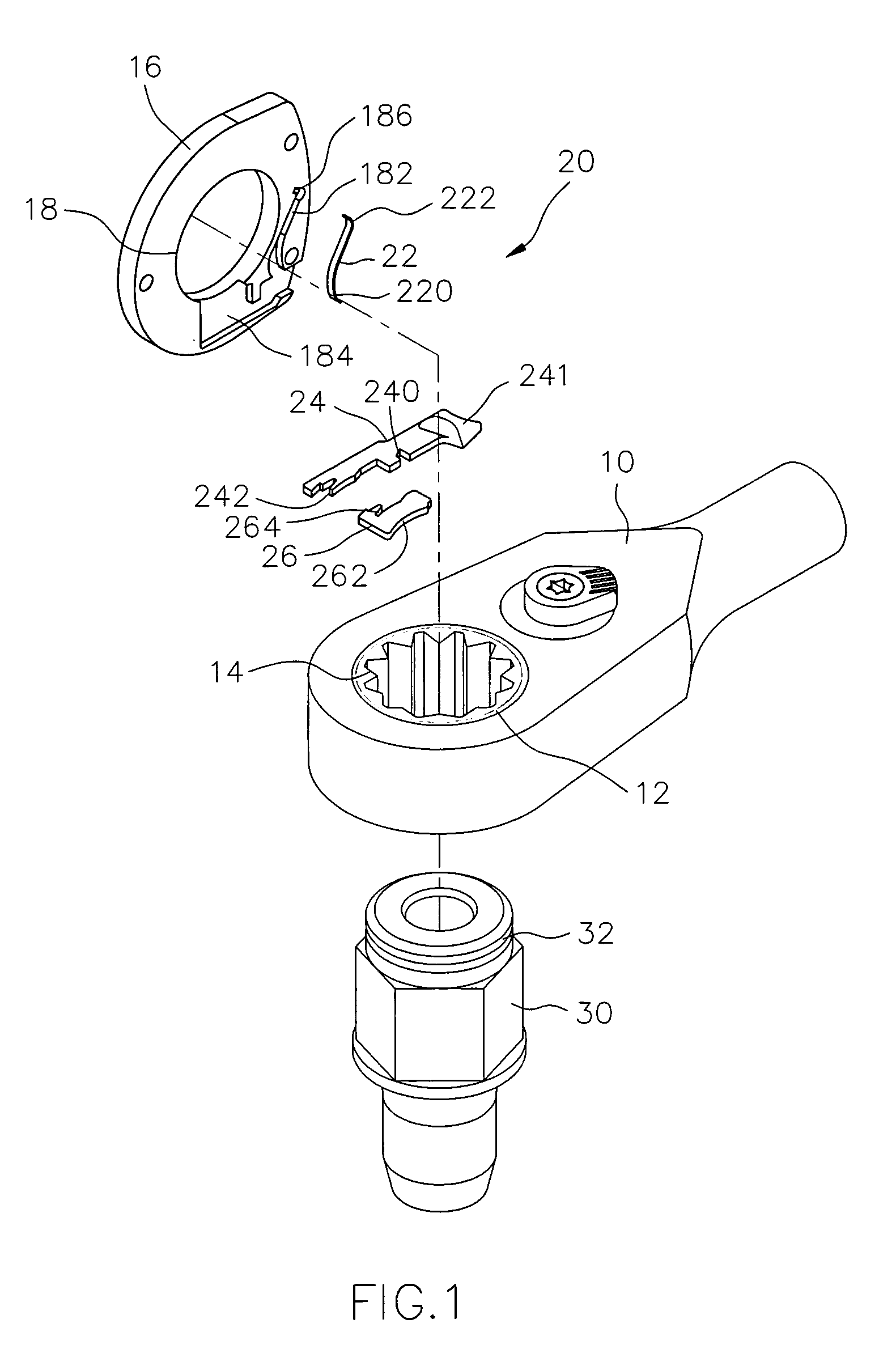
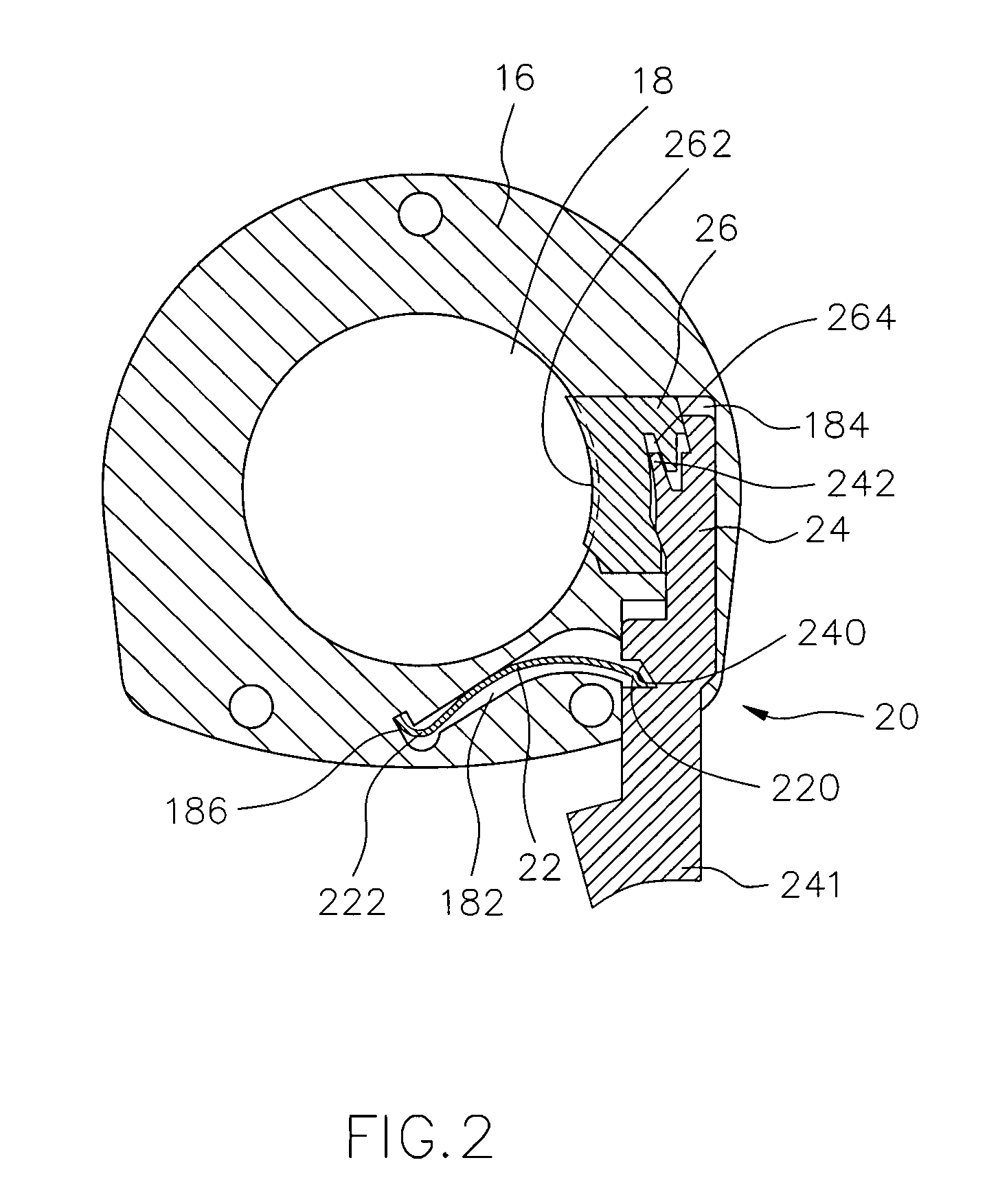
[0022]Referring to the drawings and initially to FIGS. 1 and 2, a ratchet wrench in accordance with the preferred embodiment of the present invention comprises a wrench body 10 having an end formed with a receiving hole 12, a ratchet wheel 14 rotatably mounted in the receiving hole 12 of the wrench body 10, a cover 16 mounted on the wrench body 10 and formed with a through hole 18 communicating with the receiving hole 12 of the wrench body 10, a socket 30 mounted in the ratchet wheel 14 and having an end extended into the through hole 18 of the cover 16 and formed with an annular groove 32 communicating with the through hole 18 of the cover 16, and a positioning device 20 mounted between the cover 16 and the wrench body 10 and locked on the socket 30 to position the socket 30 on the wrench body 10.

[0023]The positioning device 20 includes a locking plate 26 slidably mounted on the cover 16 and having a first side formed with an arc-shaped locking portion 262 extended into the through...


PUM


Abstract

A ratchet wrench includes a wrench body, a ratchet wheel, a cover, and a positioning device mounted between the cover and the wrench body. The positioning device includes a locking plate, a push plate, and an elastic plate. Thus, the locking portion of the locking plate is extended into the through hole of the cover and detachably locked in the annular groove of the socket to lock the socket on the cover, so that the socket is positioned on the wrench body rigidly and stably without detachment, thereby facilitating a user operating the wrench body and the socket to rotate a workpiece, such as a nut, bolt or the like.

Description

BACKGROUND OF THE INVENTION[0001]1. Field of the Invention[0002]The present invention relates to a ratchet wrench, and more particularly to a ratchet wrench having a rigid positioning effect.[0003]2. Description of the Related Art[0004]A conventional ratchet wrench comprises a wrench body having an end formed with a receiving hole, a ratchet wheel rotatably mounted in the receiving hole of the wrench body, and a socket mounted in the ratchet wheel. The socket is mounted on a workpiece, such as a nut, bolt or the like. Thus, the workpiece is rotated by the socket by rotation of the wrench body. However, the socket is not combined with the ratchet wheel rigidly and stably, so that the socket is easily detached from the ratchet wheel during operation, thereby causing inconvenience to a user when operating the wrench body and the socket to rotate the workpiece.SUMMARY OF THE INVENTION[0005]The present invention is to mitigate and / or obviate the disadvantage of the conventional ratchet w...

Claims


Application Information

Patent Timeline
IPC IPC(8): B25B13/00B25B13/46B25B23/00
CPCB25B13/461B25B23/0035
Inventor LI, YI MIN
Owner LI YI MIN
Features
  • Generate Ideas
  • Intellectual Property
  • Life Sciences
  • Materials
  • Tech Scout
  • Unparalleled Data Quality
  • Higher Quality Content
  • 60% Fewer Hallucinations
Learn More