
Surface effect ship improvements

a technology of surface effect and ship improvement, which is applied in the field of surface effect ship improvement, can solve the problems of severe degradation of ride quality and huge increase in resistance, and achieve the effect of efficient and sea-friendly

Inactive Publication Date: 2005-09-27
PAULETTE RENEE BURG
View PDF11 Cites 8 Cited by
  • Summary
  • Abstract
  • Description
  • Claims
  • Application Information

AI Technical Summary

Benefits of technology

[0007]The primary object of the instant invention is to provide a very efficient and sea kindly marine surface effect ship that is partially supported by artificially pressurized gas cushion(s).

Problems solved by technology

While not a problem in calm water, the barn door effect of the generic SES's moveable bow seal results in tremendous increases in resistance and a severe degradation in ride quality as sea state increases.

Method used


Image

  • Surface effect ship improvements
  • Surface effect ship improvements
  • Surface effect ship improvements

Examples


Embodiment Construction

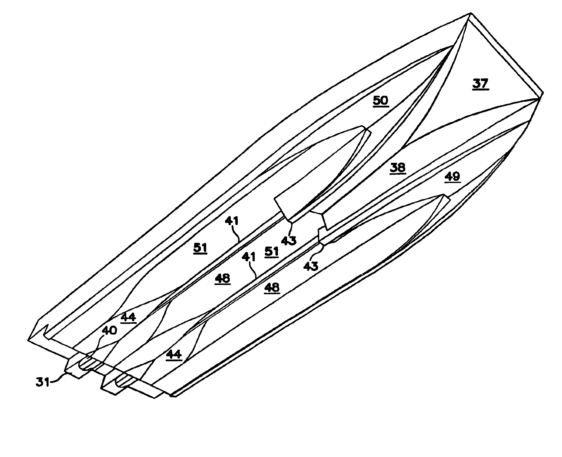
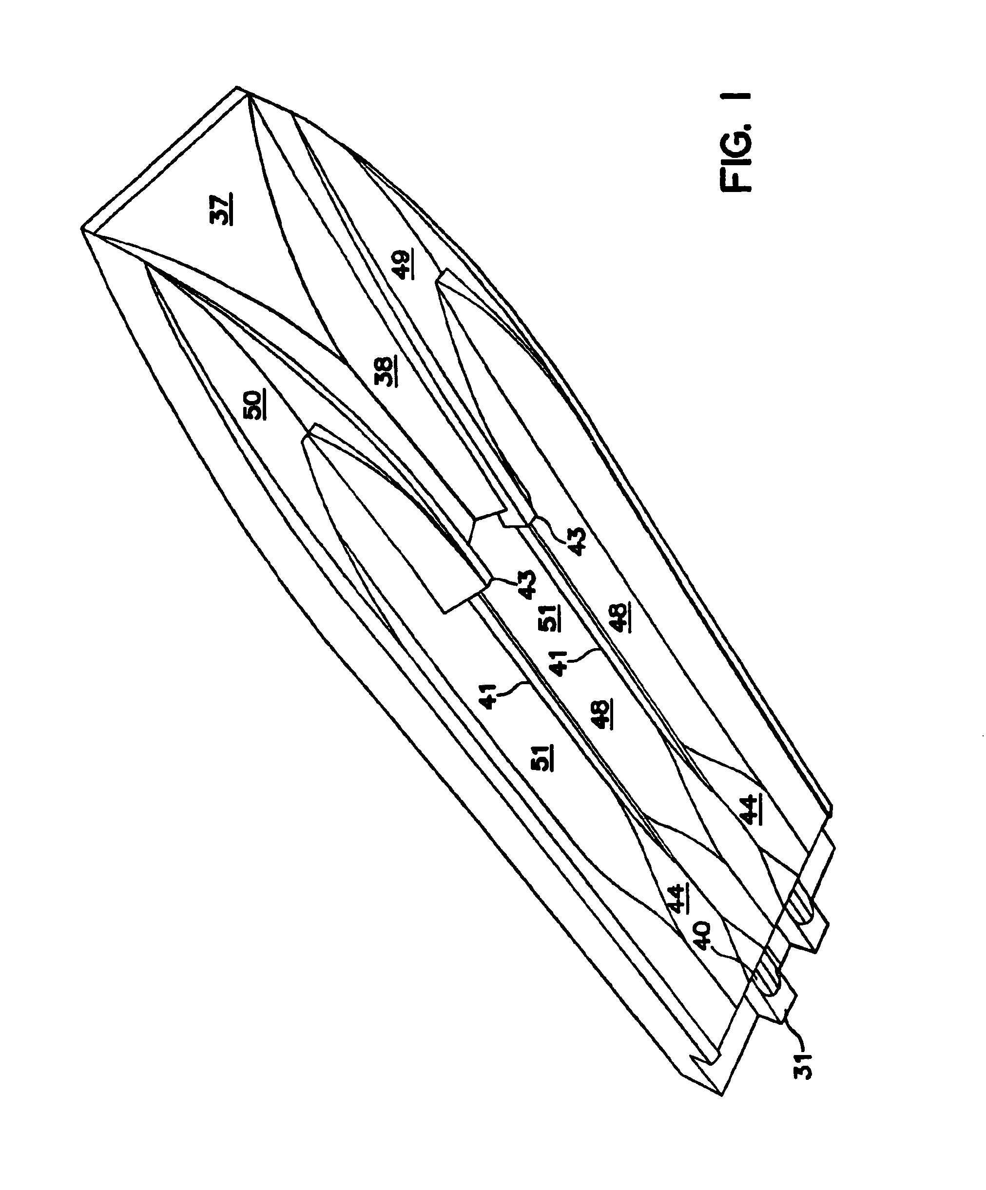
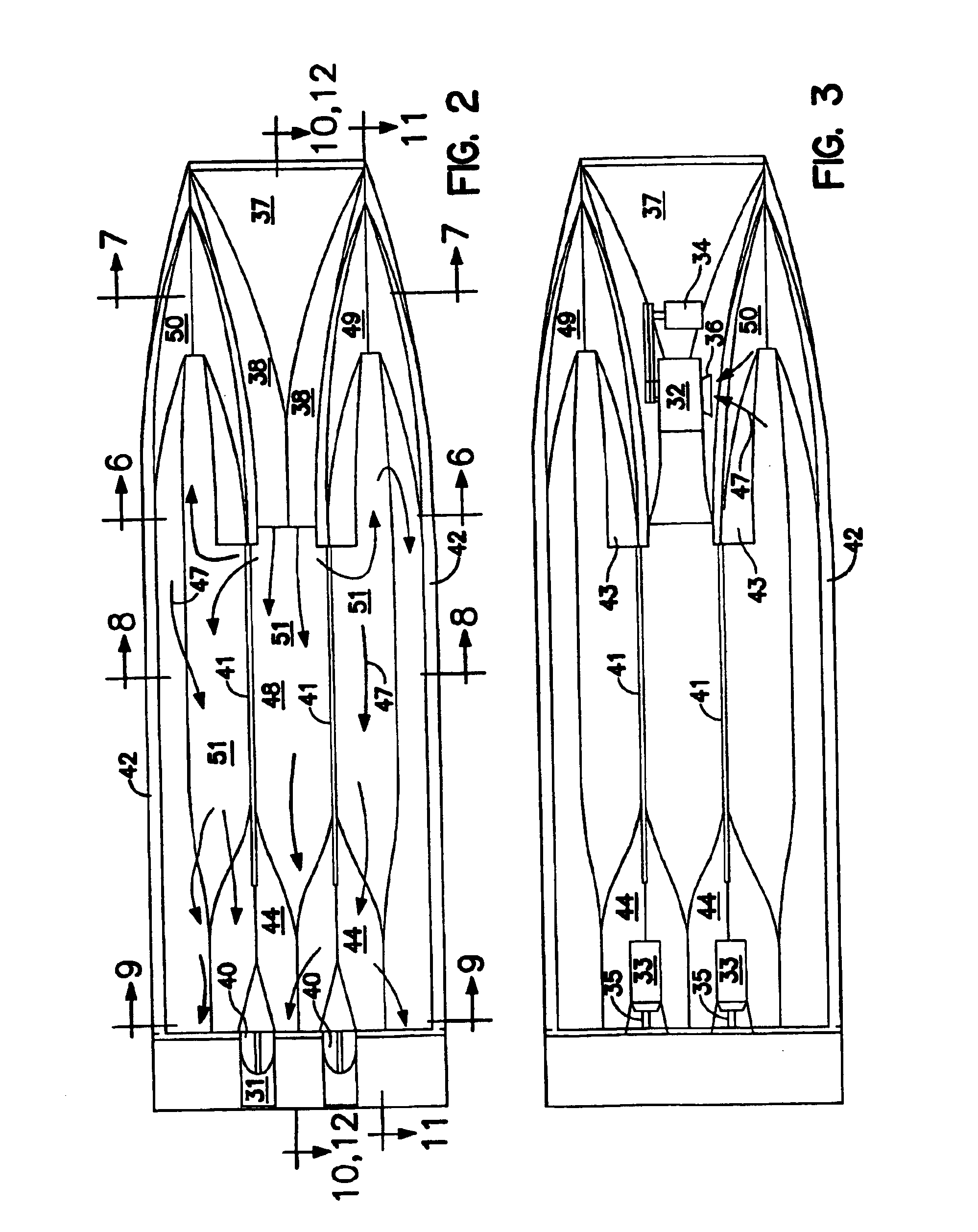
[0064]FIG. 1 presents an underside 3D perspective of the enhanced surface effect ship 37 to the instant invention. Items to note are forward extending port bow member 49 and starboard bow 50. These bow members extend forward of a gas cushion forward seal member 38. In this case the gas cushion forward seal member 38 has the preferred inverted-V shape. The inverted-V shape provides good rough sea ride qualities and also presents a shape that concentrates the water coming off of the bows 49, 50 to most effectively create a gas sealing effect. Artificially pressurized gas is supplied to the gas cushion through gas discharge openings in the aft end of the gas cushion forward seal member 38 in this preferred embodiment of the invention. Other means of supplying pressurized gas to the gas cushion 48 can be employed and are considered to be within the scope of the instant invention.

[0065]The pressurized gas is retained in the gas cushion 48 by sidehulls 42, bow members 49, 50, inboard side...


PUM


Abstract

Presented is an improved Surface Effect Ship (SES) that offers the high efficiencies of the pressurized air cushion supported generic flexible bow and stern seal SES but without the generic SES's shortcomings that are due largely to its 80 percent total hull width flexible bow and stern seals. This is accomplished in the instant invention by use of forward extending rigid bow members positioned both sides of a pressurized hull supporting gas cushion where the width of the sidehulls make up a majority of the width of the instant invention improved surface effect ship with the remainder, less than 35 percent of vessel width normally, made up by a gas cushion forward seal member disposed between the bow members. Gas cushions may extend forward into undersides of the sidehull bow members to further reduce wetted area resistance. Longitudinally oriented fluid fences may be incorporated to at least partially separate portions of the gas cushion and thereby dampen pressure perturbations in the gas cushion(s). A third bow member may be utilized between port and starboard sidehulls.

Description

CROSS REFERENCE TO OTHER APPLICATIONS[0001]This application is a continuation-in-part to U.S. application Ser. No. 10 / 274,654 filed Oct. 21, 2002 now abandoned; Ser. No. 10 / 286,712 filed Nov. 1, 2002 now abandoned; Ser. No. 10 / 337,490 filed Jan. 7, 2003; and Ser. No. 10 / 777,426, filed Feb. 11, 2004.BACKGROUND OF THE INVENTION[0002]Marine Surface Effect Ships (SES) in their generic form have a upper hull that is rather flat on its underside with downward extending asymmetrical catamaran sidehull portions either side. These asymmetrical sidehull portions are connected transversely fore and aft by flexible seals. The boundary of the space thus formed is pressurized with air supplied by powered blowers to thereby form a deep air layer between the hull and the water's surface. This results in a vessel that has little water contact and is therefore quite efficient at high speeds in calm water.[0003]Major shortcomings of the generic SES are that: 1) The wide barn door effect of the flexibl...

Claims


Application Information

Patent Timeline
Patent Type & Authority Patents(United States)
IPC IPC(8): B60V3/06B60V3/00
CPCB60V3/06B63B1/322B63B1/38B63B2001/206Y02T70/10
Inventor BURG, DONALD E.
Owner PAULETTE RENEE BURG
Learn More