
Archery bow and arrow stand

a technology for archery and arrows, applied in the field of archery bows and arrow stands, can solve the problems of complex bows used, and achieve the effects of prolonging the efficiency of the gear mechanism, preventing damage, and facilitating offs

Inactive Publication Date: 2005-09-27
GILBERT RALPH D
View PDF18 Cites 32 Cited by
  • Summary
  • Abstract
  • Description
  • Claims
  • Application Information

AI Technical Summary

Benefits of technology

[0009]When shooting archery in competition or simply for recreation, often very complex bows are used with a variety of very delicate aiming devices attached to the bow. These devices, once sighted for a target, are easily offset if they are bumped or if the archery bow is dropped or falls over. In addition, the ends of some archery bows have very intricate gear mechanisms, especially compound bows, that should not be exposed to dirt or the ground any more than necessary to prolong the efficiency of the gear mechanisms and to keep the bowstrings clean. Therefore, a need is presented to provide a bow holder that keeps a bow off the ground, sets the bow without a spring mechanism at a level easily reached by an erect shooter, and which does not cause any bump or other trauma or impact to the bow when placed in and drawn out of the bow holder.
[0010]A first objective of the bow and arrow stand is to provide a bow support which will allow the bow to be held above the ground readily accessible to a standing archer which does not engage the bow or bowstring with a hook and also prevents the aiming and sighting attachments from becoming dislodged or moved in the slightest during engagement and disengagement. A second objective is to provide an attached bow quiver and an accessory tray to provide the archer access and carriage of his entire shooting supplies and tools in a singular device. A third objective is to provide the device easily engaging the ground by simply stepping on the horizontal arm to engage the archery bow and arrow stand into the ground.

Problems solved by technology

When shooting archery in competition or simply for recreation, often very complex bows are used with a variety of very delicate aiming devices attached to the bow.
In addition, the ends of some archery bows have very intricate gear mechanisms, especially compound bows, that should not be exposed to dirt or the ground any more than necessary to prolong the efficiency of the gear mechanisms and to keep the bowstrings clean.

Method used


Image

  • Archery bow and arrow stand
  • Archery bow and arrow stand
  • Archery bow and arrow stand

Examples


Embodiment Construction

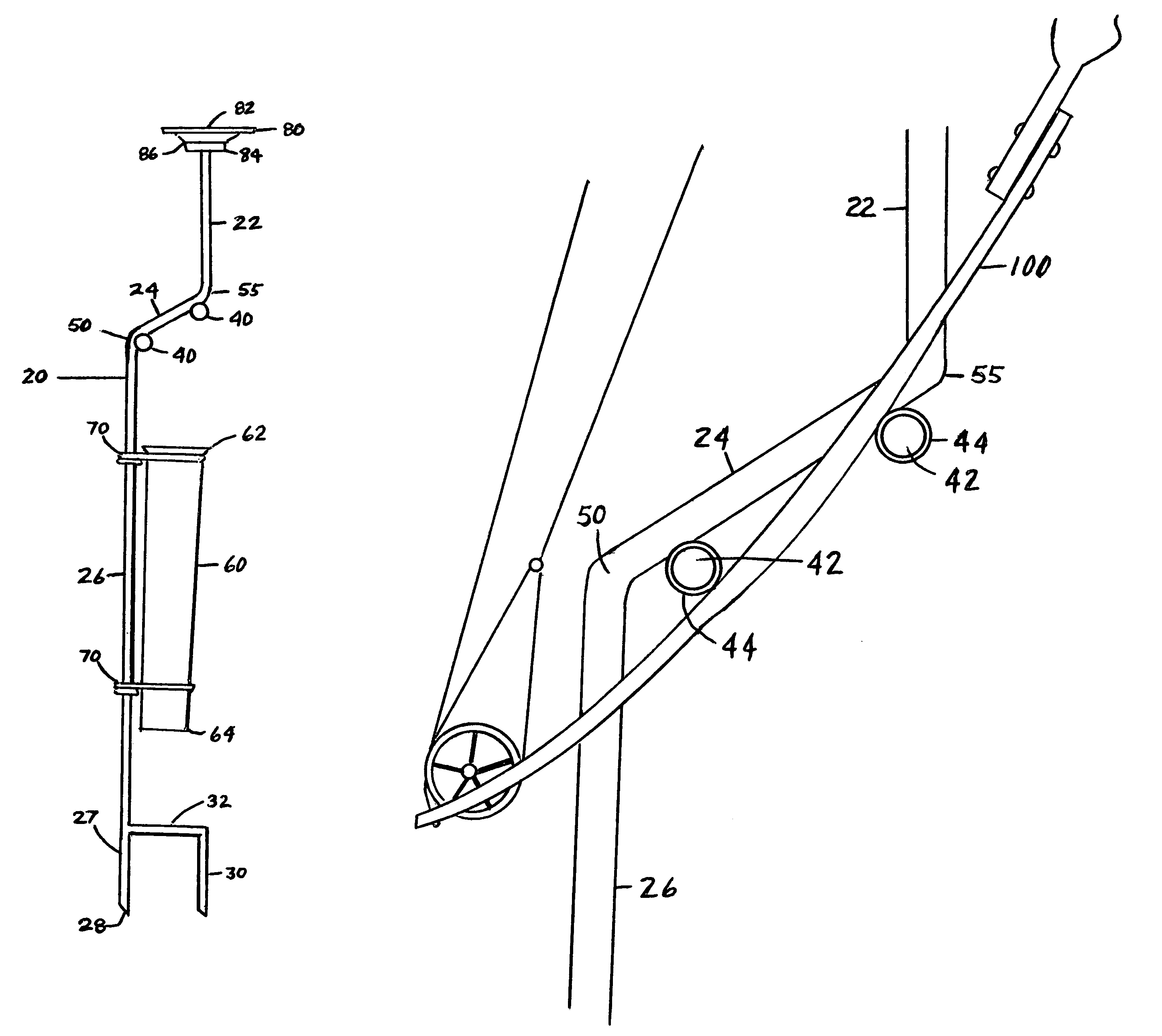
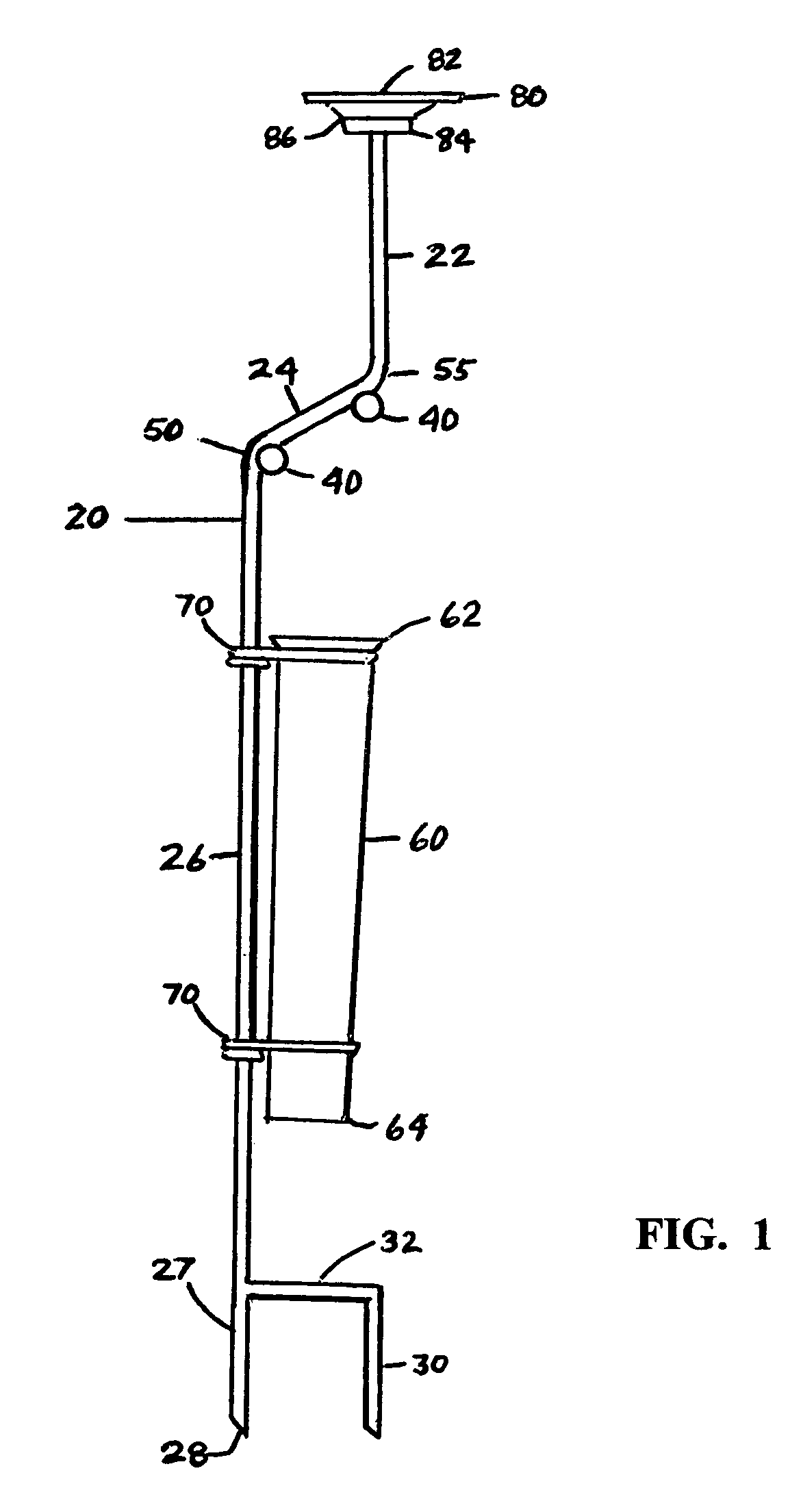
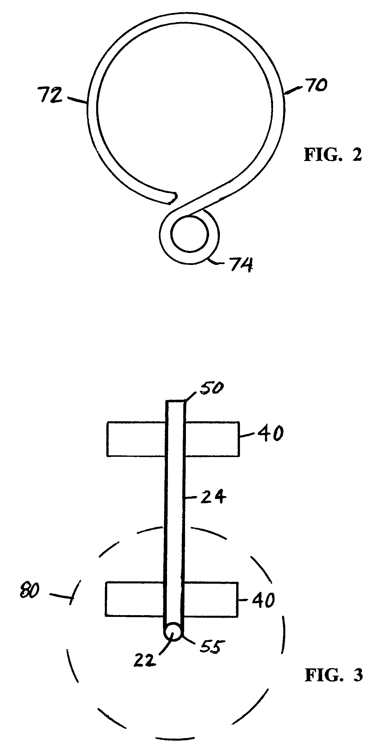
[0016]A bow and arrow stand, shown in FIGS. 1–4 of the drawings, engaging the ground and holding an archery bow 100 in an erect and upright position without contact with the bow string or the end of the bow, comprises essentially a vertical support shaft 20 with an angular middle portion 24, an upper vertical portion 22 and a lower vertical portion 26, the lower vertical portion 26 having a ground end 27 tapered into a point 28 to be inserted into the ground, two padded horizontal members 40 attached to the angular middle portion 24, an arrow quiver 60 suspended from the lower vertical portion 26 by at least two detachable quiver brackets 70, a secondary ground spike 30 with a horizontal arm 32 attaching the secondary ground spike 30 to the lower vertical portion 26 and also to provide a place for foot pressure to drive the secondary ground spike 30 and the ground end 27 of the lower vertical portion 26 into the ground, and a magnetic accessory bowl 80 attached to the upper vertical...


PUM


Abstract

A bow and arrow stand, engaging the ground and holding an archery bow in an erect and upright position without contact with the bow string includes a vertical support shaft with an angular middle portion, an upper vertical portion and a lower vertical portion with a ground end tapering into a sharp point which is inserted into the ground, two padded horizontal members attached to the angular middle portion, an arrow quiver suspended from the lower vertical portion, a secondary ground engaging spike with a horizontal arm attached to the lower vertical portion, and a magnetic accessory bowl attached to the upper vertical portion to hold archery tools and accessories.

Description

CROSS REFERENCE TO RELATED APPLICATIONS[0001]Provisional Patent Application Ser. No. 60 / 410 / 355 filed Sep. 13, 2002.BACKGROUND OF THE INVENTION[0002]1. Field of Invention[0003]A bow and arrow stand, engaging the ground and holding an archery bow in an erect and upright position without contact with the bow string includes a vertical support shaft with an angular middle portion, an upper vertical portion and a lower vertical portion with a ground end tapering into a sharp point which is inserted into the ground, two padded horizontal members attached to the angular middle portion, an arrow quiver suspended from the lower vertical portion, a secondary ground engaging spike with a horizontal arm attached to the lower vertical portion, and a magnetic accessory bowl attached to the upper vertical portion to hold archery tools and accessories.[0004]2. Description of Prior Art[0005]The following United States patents were discovered and are disclosed within this application for utility pat...

Claims


Application Information

Patent Timeline
Patent Type & Authority Patents(United States)
IPC IPC(8): F16M13/00A47B81/00F41B5/14
CPCA47B81/005F41B5/14
Inventor GILBERT, RALPH D.
Owner GILBERT RALPH D
Learn More