Cable and apparatus interface environmental seal

a technology of environmental seals and cables, applied in the direction of cable junctions, connection contact material, coupling device connections, etc., can solve the problems of affecting the sealing system, and affecting the sealing effect of the sealing system at the limit of the specified temperatur

Active Publication Date: 2005-09-27
COMMSCOPE TECH LLC
View PDF21 Cites 97 Cited by
  • Summary
  • Abstract
  • Description
  • Claims
  • Application Information

AI Technical Summary

Benefits of technology

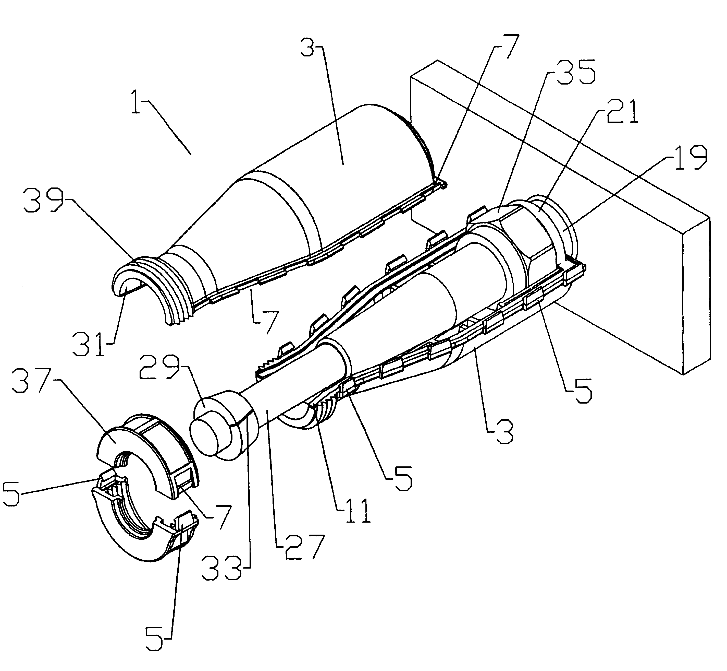
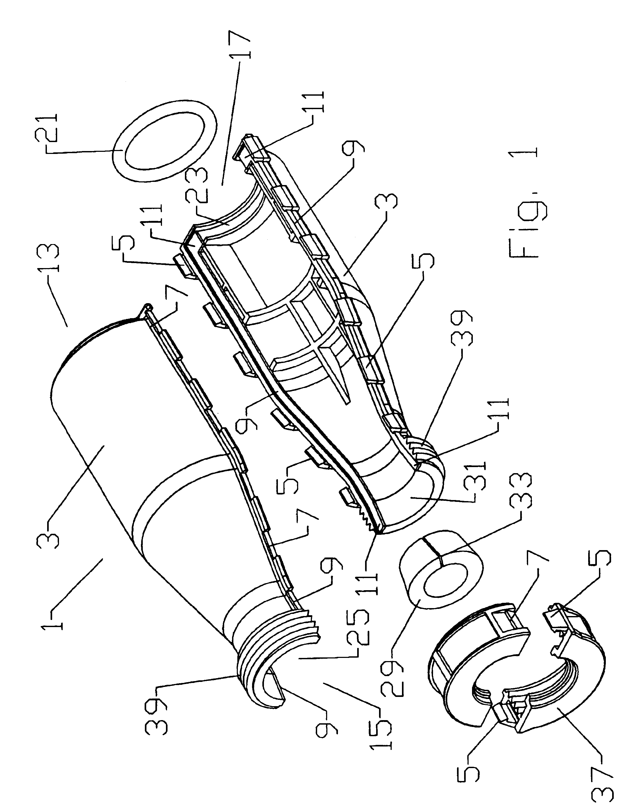
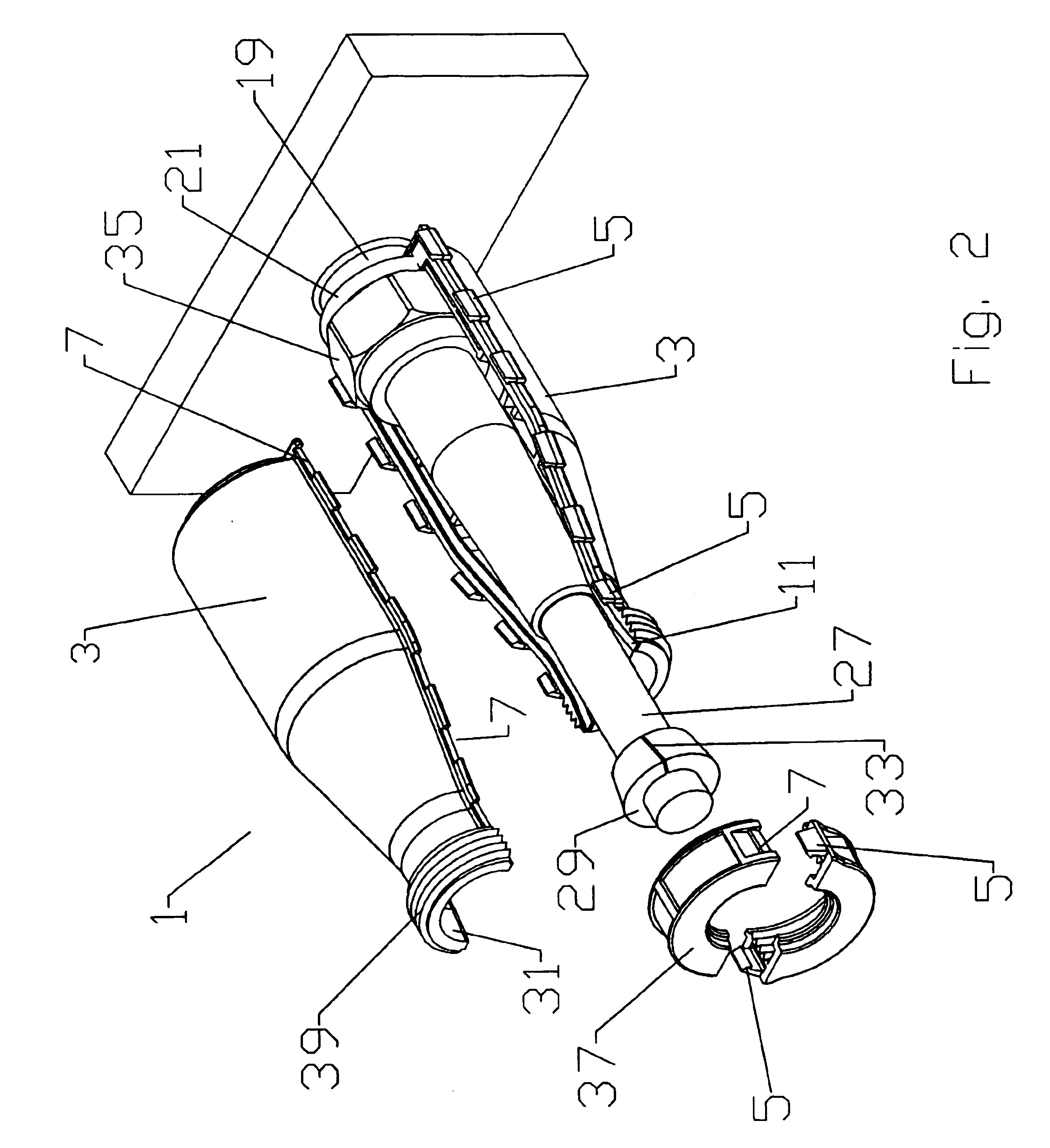
[0018]The size of the cable end opening 25 is dependant upon an expected cable 27 outer diameter. Unlike the connector body 19 outer diameter, the cable 27 outer diameter may vary within a range depending upon the different cable 27 configurations that are available. For example, an outer sheath of the cable 27 may vary in thickness and or elasticity. Also, different cable 27 outer conductor corrugation configurations may vary the cable 27 outer diameter. Therefore, a seal in the form of a cable end gasket 29 is adapted to tightly seal against a range of diameters. The cable end gasket 29 is dimensioned to be compression fitted between a conical cable end gasket surface 31 formed by the two shell halve(s) 3 and the outer diameter of the cable 27. A slit 33 in the cable end gasket 29 allows the cable end gasket 29 to be fitted over a cable 27 with a pre-attached connector 35. Because the cable end gasket 29 is compressed into a conical space, the cable end gasket 29 can adapt to a range of different cable 27 diameters and still form a reliable seal despite the presence of the slit 33. The cable end gasket 29 may be formed using a material with a high temperature rating such as silicon or epdm.
[0019]The cable end gasket 29 is compressed into a sealing position between the cable 27 outer diameter and the cable end gasket surface 31 by a nut 37 that threads onto threads 39 formed in the cable end 15 of the two halve(s) 3. To allow the nut 37 to be fitted over a cable 27 with a pre-attached connector 35, the nut 37 is formed in two parts which snap together, using an interconnection that may be similar to that used for the two shell halve(s) 3. To maximize strength of the nut 37 connection upon the threads 39, the thread 39 starting point may be located at a position on the two shell halve(s) 3, and or on the corresponding threads of the nut 37, whereby when the nut 37 is fully bottomed onto the threads 39, the split plane between the two parts of the nut 37 and the split plane between the two shell halve(s) 3 will be normal to each other.
[0020]In use, the sealing assembly 1 is prepared for interconnection by applying the edge gaskets 11 (if not pre-applied at time of manufacture) to one or both shell halve(s) 3. The apparatus end gasket 21 is installed over the connector body 19 outer diameter (before the cable 27 is connected to the connector body 19) and the cable end gasket 29 is fitted over the cable 27 via the slit 33. The two shell halve(s) 3 are snapped together around the attached cable 27 and connector body 19 with the apparatus end gasket 21 positioned in the apparatus end groove 23. The cable end gasket 29 may then be slid along the cable 27 into contact with the cable end gasket surface 31. Next, the two nut 37 parts are snapped together, around the cable 27. Finally the nut 37 is threaded onto the threads 39, compressing the cable end gasket 29 into a sealing configuration between the cable end gasket surface 31, the cable 27 outer diameter and the nut 37. Each of the sealing assembly 1 installation operations described herein may be quickly performed by hand, without the aid of any additional or specialized tools at the time the cable 27 is interconnected with the apparatus. Further, the resulting assembly uses no gel but achieves a reliable seal upon a range of cable 27 diameters and may be inexpensively adapted for use in high temperature environments via selection of widely available gasket materials having appropriate temperature ratings.
[0023]From the foregoing, it will be apparent that the present invention brings to the art a sealing assembly 1 for cable to apparatus connections having improved performance and significant manufacturing and installation cost efficiencies.

Problems solved by technology

Electrical interconnections are subject to degradation from environmental factors such as moisture, vibration and repeated expansion and contraction from daily temperature changes.
However, gel sealing compositions are typically limited to environments where the temperature will be 60 degrees Celsius or less.
Also, in the frequently vertical configuration of a cable to antenna attachment, a sealing system using gel at the limit of the specified temperature may become compromised due to gel migration and or leakage.
Gel seals are typically not re-usable.
Feed and or control cable connections to antennas are also subject to environmental degradation.
The reliability of this form of manually applied seal is dependant upon the training and motivation of the installation personnel, which may be negatively influenced by the often hazardous and or environmentally exposed locations, for example high atop radio towers, where -they are installed.
Further, once installed, a sealing wrap must be destroyed to again access the interconnection.

Method used


Image

  • Cable and apparatus interface environmental seal
  • Cable and apparatus interface environmental seal
  • Cable and apparatus interface environmental seal

Examples


Embodiment Construction

[0013]Connections to an apparatus, for example an antenna, are typically made to a connector body mounted to an exterior surface of the antenna. Because the connector body is flush against a surface, a cable to cable interconnection sealing assembly that tapers at either end to a cable diameter is unusable.

[0014]As shown for example by FIGS. 1-3, a sealing assembly 1 according to one embodiment of the invention has two shell halve(s) 3 adapted to snap together around a desired interconnection space. The shell halve(s) 3 may be formed, for example, from an impact and UV degradation resistant plastic using injection molding.

[0015]A range of different connections between the shell halve(s) 3 may be used, for example, a plurality of hook tab(s) 5 which mate to a corresponding plurality of hook edge(s) 7. Alternative forms of connection may include other forms of snap together interconnection well known in the art and or a hinge that connects the two shell halves along one edge.

[0016]The...


PUM


Abstract

A seal assembly adapted to seal around an interconnection between a cable and an apparatus. The seal assembly formed from two shell halves which join together around the interconnection that are sealed by a gasket against a connector body attached to the apparatus at an apparatus end and another gasket against the cable at a cable end. The cable end gasket is adapted to be pressed between the cable and a conical cable end gasket surface by a nut which threads onto a thread formed on the two shell halves. The nut and cable end gasket are adapted to attach to the cable without passing over a connector attached to the cable end. The cable end gasket has a slit and the nut is formed from two parts which join together, around the cable.

Description

BACKGROUND OF INVENTION[0001]1. Field of the Invention[0002]The invention relates to sealing the interconnection between cables and apparatus, for example feed and or control cables interconnected with an antenna. More particularly, the invention provides a re-usable snap-on tool-less weather proof environmental seal assembly for a cable to apparatus interconnection.[0003]2. Description of Related Art[0004]Electrical interconnections are subject to degradation from environmental factors such as moisture, vibration and repeated expansion and contraction from daily temperature changes.[0005]Environmental seals consisting of an outer enclosure that surrounds an electrical interconnection have been used, for example, to surround a cable end connector to cable end connector interconnection. The, for example, injection molded plastic enclosures have been configured to surround the cable interconnection with two halves in a clamshell hinged configuration that is sealed with a gel compositi...

Claims


Application Information

Patent Timeline
Patent Type & Authority Patents(United States)
IPC IPC(8): H01R4/58H01R12/00H01R9/03
CPCH01R13/512H01R13/52H02G15/113
Inventor GOODWIN, KEVINCOX, AL
Owner COMMSCOPE TECH LLC
Why Eureka
Try Eureka